Scissor Lift Wind Load Analysis
Analysis
Objective
Although usually not necessary, given its high-value electronics equipment, a detailed CFD wind-load analysis was done on this commerical scissor lift.
Wind load forces from this CFD consulting study were then used to calculate stability loads for a safe operating range under human operation.. The CFD study allowed the client to give a wind rating with high confidence. It additionally saved the client thousands of dollars since they did not need to do physical wind tunnel testing.
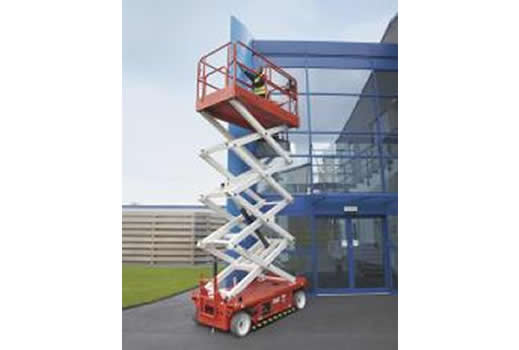
The model was built with client supplied CAD geometry (see Figure 1).
The tipping force was calculated at varying extension heights. The computational fluid dynamics (CFD) analysis was run to determine the force on the structure at varying wind speeds. These forces were verified against wind load calculations from ASCE 7-02, Minimum Design Loads for Building and Other Structures. A typical calculation table can be seen below in Table 1.
Typical CFD simulation results can be seen in the figures below. Air flow traces and static pressure can be seen in Figure 2 and a typical velocity magnitude plot can be seen in Figure 3
Keywords: CFD Consulting, Computational Fluid Dynamics, Fluid Mechanics, ASCE Wind Load Analysis, ASCE 7-02, Stability Analysis, Tipping Analysis, US Air Force,
PDF Download


