Nonlinear & Transient Dynamic Consulting
At Predictive Engineering, we pride ourselves for our ability to idealized complex structures and systems into accurate numerical models. When it comes to nonlinear, transient dynamic analysis, we are experts in getting LS-DYNA to do the near impossible.
We have direct validated experience in:
- Drop-test analysis per 49 CFR 173 or MIL-STD-810E
- Airplane seat analysis per TSO-C127a / SAE AS8049A / 14 CFR Part 25.562 for the 16g sled test
- Blast analysis for protective design per PDC-TR 06-08 and CSA S850-12
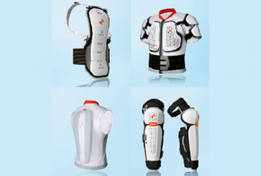
- Nonlinear material modeling of plastic, elastomeric and foam modeling for the sporting goods industry
- Simulation of medical equipment from orthopedic screws, endoscopic tools (cables and tubes), syringes, cardiac tools and dental equipment
- Extensive experience in nonlinear analysis of plastics from multi-shot assemblies, thread designs or drink cups
- Impact analysis of a broad range of systems from composite structures, structural steel frames, engine stands, mining digger teeth, cameras and locomotive fuel tanks
- Burst containment analysis on high-speed rotating turbines and medical equipment (x-ray scanning equipment)
- Fracture simulation in glass and ceramic composites
- Pyro-shock analysis for military devices
- Hyperelastic seal design (e.g., O-rings) for medical devices, truck components and coffee cups
Our experience has been hard fought over 20 years of continuous use of LS-DYNA in solving some of the toughest nonlinear static and dynamic analysis problems. If you would like to know more, please feel free to contact us.
Nonlinear, Transient Dynamic Analysis of Triple-Deck Shaker System
Although shaker screens are proven technology, this technology is often based on the “Edisonian Approach” of extensive laboratory effort coupled with in-house engineering expertise to arrive at a new shaker design. This approach has it merits but is slow and sometimes expensive. Our client, was developing a new shaker screen system that could rapidly screen rock coming out of a jaw-crusher. Their proposed shaker was triple-deck system driven by a three-axis counter-weight drive. Normally, such drive systems create an aligned force that sinusoidally varies and thus are animable to analysis via modal frequency (aka frequency analysis). Performing a modal frequency analysis is classical linear FEA consulting work and not challenging to most FEA consultants. However, their chosen drive system positions the counterweights to create an elliptical force loop that facilitates varying rock dwell times along the length of the deck screens. Since the force direction varies in time over 360 degrees, a nonlinear transient analysis was required. Now, the project is challenging since nonlinear FEA consulting work is much more complex. The counter-weight forces were idealized as cos and sin functions offset by 90 degrees. The model captured the complete dynamic response of the shaker and provide full-field stress results during operation. Stress values were then used for durability analysis of the shaker and also for optimization of plate structures. Analysis results tied closely to experimental results from the client. With this validated model, the client is confident that in-field fatigue failures can be avoided and the shaker will work as design right out-of-the-gate. As a side note, this project started out with the assumption that it would only require linear FEA engineering services and fortunately for the client, Predictive had decades of experience in nonlinear FEA services and could quickly address the additionally complexity of the analysis project.
LS-DYNA Class October 16-26, 2023
Predictive Engineering hosted their yearly LS-DYNA Class with simulation engineers from JPL-Nasa, Medtronic, Karman-Systima, Sonos and ArcelorMittal. The LS-DYNA class used our revised notes that covers analysis sequences from implicit to explicit.
Underwater Tank Burst Analysis with Smooth Particle Hydrodynamics (SPH)
Our client is a large manufacturer of gas cylinders and, as part of their manufacturing process, pressure test each tank within a chamber that allows submerged (under water) and air testing. Occasionally, these high-pressure cylinders will burst. Due to safety concerns, our client wanted to understand the safety margins of their new test chamber as the tanks might burst in air and under water. A major concern was to maintain the integrity of their plexiglass (PMMA) inspection port window when impacted by tank burst fragments. Predictive Engineering was tasked with this project due to materials consulting experience from laboratory to simulation. The tank burst simulation was rather simple by assuming the largest possible fragment and then applying a pressure pulse to eject the fragment. The water medium was modeled using a mesh-free method termed smooth-particle-hydrodynamics or SPH. This numerical technique is common for bird strike analysis where the bird is modeled as semi-frozen water. SPH allows one to model fluids or solids that can completely disintegrate under load. In this burst analysis, SPH captures the energy of the tank fragment and creates a pressure pulse within the test chamber. The resulting SPH water sloshing stresses the tank and allowed us to determine the chambers safety-margin under submerged burst conditions. This is a prime example of SPH usage as a loading technique to apply load to the structure of interest, whether tank sloshing, bird-strike, projectile penetration, hydraulic slamming, etc. Predictive specializes in this type of nonlinear FEA analysis with 30 years of academic, laboratory and industry experience. For the plexiglass fracture analysis, a tank fragment was impacted against the viewport at several angles to determine a worst-case scenario. Under the most extreme conditions, the PMMA port would show cracks but not fracture. Our engineering report indicated that the test chamber was well designed and if required, it is not necessary to burst test their high-pressure cylinders under water.
Composite Overlay Pressure Vessel (COPV) Autofrettage and Burst Analysis
Aviation, aerospace, automotive, etc. are all moving toward composite pressure vessels. Although expensive, the advantages of composite overlay pressure vessels (COPV) can’t be denied. Our client required an aerospace grade analysis of the COPV, Type III vessel thru its complete manufacturing and test process. The analysis work started with an axisymmetric model for quick design optimization and then progressed to a full 3-D model of the COPV. Challenges for the client was the nonlinear plastic deformation of the aluminum liner to create a residual compressive stress state (autofrettage) and then final burst prediction. These analysis requirements let our client to contract with Predictive Engineering due to our experience in nonlinear FEA consulting, composite engineering and damage and fracture mechanics. The last part leveraged our knowledge of using NASGRO software for crack growth predictive. For our FEA services team, the highlight of this project was the validation of the composite burst model against our client’s experimental data. Not only did it show close correlation but was also generated a tighter fit than their own internal prior work.
Nuclear Power Plant Pressure Relief Door: Slam and Stop Analysis
Stopping a 2,000 lb door swinging open at 30 mph can be easy or it can be hard. Our client was faced with a limited design envelope and very stringent nuclear safety design requirements for door slam arrestment. Their first challenge was how to determine the door’s velocity given that at a defined internal pressure, the door’s opening mechanism would be triggered and the door would swing open into the non-pressurized operating galley. The second challenge was the analysis of the slam-stop mechanism that would dissipate some of the door’s kinetic energy thru crush tubes and then latch onto the door to prevent its bounce back. Thus, our client required simulation consultants with expertise in transient, dynamic CFD and with nonlinear, transient dynamic FEA. Predictive’s CFD engineer built the transient CFD model using a moving mesh technique which allowed the door to be dynamically accelerated due to the containment pressure into the open galley. Final door velocity from this analysis was then used as the starting point for our nonlinear analysis FEA consultant to simulate the behavior of the crush tubes and the door stop analysis mechanism. After extensive design optimization of the system, a final solution was obtained for manufacturing.
Transportation Analysis of Mobile Cable Storage System
Although the Federal Motor Vehicle Safety Standards (FMVSS) are well known, there are also many other regulations for the transportation of cargo, such as 49 CFR-I Protection Against Shifting and Falling Cargo. Our client has recently experienced an incident where their cargo had shifted and wanted to develop a better cargo tie-down system. Based on a full nonlinear, transient dynamic FEA model of their system along with standard tensioned steel and polyester straps, it was determined that the Federal Motor Carrier Safety Administration (FMCSA) regulations could be exceeded with just a few strategically placed straps.
Dynamic Analysis of Cable Reel Racking System
A workplace culture of safety is vital to the long-term success of any corporation. When engineers identify a potential hazard that cannot be evaluated using hand calculations or internal resources, Predictive Engineering can provide simulation expertise that few companies can match. Our client was a major commercial wire supplier and used a series of racking system where large wire reels would payout wire to various customer requirements. The racking system holds four reels, each weighing up to 6,500 pounds. During the take-up operation a reel can rotate at up to 40 rpm as wire is pulled from the reel on the rack by the powered take-up reel on the shop floor. Knots, sporadically found in the reels on the rack, can stop both the reel on the rack and, due to the coupling by the wire cause the powered take-up reel on the shop floor to almost instantaneously stop during the take-up operation. These “upset” events were sporadic but from an operator perspective, a bit scary to watch. To capture the mechanical behavior of this upset event, a transient, dynamic nonlinear model of the system was built in LS-DNA. Results showed that these events generated plastic deformation in the racking system, but that collapse was unlikely in the low number of upset cycles. This was a prime example where our FEA expertise allowed us to save the client hundreds of thousands of dollars since we were able to show that their existing system was fit for service.
Heavy Steel Plate Forging Analysis
Our client was interested in having an independent failure assessment of their die assembly. Our objective was to demonstrate that the 5,000 ton die could operate for thousands of cycles. The die material was a standard high-strength, low-alloy tool steel; similar to ASIS 4140 but with additional Ni, Cr and Mo and a touch of V (0.1%) for grain refinement. Both hot (1,800 F) and cold (400 F) forming simulations were conducted. As the blank was forged, stress concentrations were noted in the die block bolt holes. As could be expected, the most severe operation condition is that at cold forming since the higher temperatures at hot forming, relaxes the elastic modulus of the die material sufficiently to lower the die closing stresses. Since the fatigue requirements were low-cycle (<10,000 cycles), our recommendation was to limit the forging load such that the die only reached 90% of its yield strength.
FMVSS 210 – Ensuring Cadaver Identification
Federal Motor Vehicle Safety Standards (FMVSS) are wonderful things and thousands of people are alive today thanks to these standards. In the human, land-based transportation industry, if it has a seat with a human in it, it has to pass the FMVSS 210 standard. Although one may think of it as a seat pull test it’s really known as a seat anchor test where the load is applied thru the seat belts. The base load is 5,000 lbf per person. If one assumes that the average person or anthropomorphic test device (ATD) at the 50th percentile is 77 kg (170 lb), then the FMVSS 210 assumes that the seat’s design load is 29g. This is impressive given that it is doubtful one would survive a 29 g deceleration. We have done several FEA consulting projects using the FMVSS 210 standard (LS-DYNA simulations) and it always amazes us how the seats can hold together. For example, a three-person bus seat has to withstand a combined pull load of 15,000 lbf and yes – the seat anchors pass.
Composite Analysis from Experimental to Delivery Structure
At Predictive Engineering, we are generalists with simulation skill sets from submarines, medical instruments, FFG(X) ships to aviation and space. As part of this portfolio work, we occasionally get involved with ITAR work. This project started with the development of the composite material models via validation of FEA models of tensile and 4-Pt bend test coupons. With this foundation, the composite aerospace structure was analyzed under transient dynamic loading using the nonlinear implicit method. Why implicit? The loading regime was in the order of 50 of milliseconds and it wasn’t necessary to capture frequencies above 500 Hz, hence, we could use an implicit time step of 0.2 millisecond and have a solution with 250 steps and a quick solve time. The results compared favorable against the experimental tests.
Solid-State Physics of Advanced Energy Storage Systems: How Flat is Flat?
Working in nanometers is just a matter of scale but try telling that to the FEA code. In solid-state physics where disks are pressed together, surface flatness controls the physics and the mechanics of the structure. In this FEA services work, our objective was to measure the contact force required to flatten a disk in the nanometer range (vertically) with a disk in the mm diameter (horizontally). Disk topography was imported with a point cloud and then converted into a FEA mesh via a custom built script by one of our engineers. This allowed us to execute a Design of Experiments (DoE) on how surface topography relates to the contact flattening force. As one can imagine, the flatter the disk, the better the physics; however, if one pushes too hard, the disk will crack. This was the whole gist of the project – How Flat is Flat given the DoE. Very interesting exploration into nonlinear contact mechanics, scripting and the world of solid-state physics.
XFEM – Extended FEM for Crack Propagation Through Complex Structures
Predictive Engineering recently completed an engineering services contract with a large US Navy shipbuilder where we used XFEM to make structural integrity predictions. The challenge was to quantitatively calculate the energy required to propagate a crack from a hull engine vent up through the panel and across a stiffener. The goal was to demonstrate that the crack could be arrested prior to reaching the main deck. The work was backed up via fracture mechanics calculations and static work calculating the localized mode I stress intensity factor (KI). Using XFEM we were able to optimize the crack arrestor bulb from somewhat massive dimensions to something that could be reasonably manufactured and thereby shaving a few tons of weight off the FFG(X)’s design.
SCat Gun Test of Optical Lens Assembly
Soft Catch (SCat) gun testing involves blasting components out of a 155 mm Howitzer cannon with a M199 gun tube and then decelerating these components using 540 feet of catch tubes. The method allows engineers to put projectiles through massive acceleration loads and safely recover the projectiles by slowing them down with a system of diaphrams, pressurized air and water chambers. Although the SCat gun saves time and money over previous test methods, it is still comes with a massive price tag.
Blast, impact and high accelerations are bread-and-butter analyses for LS-DYNA. However, working with glass made this project a bit more interesting. While the yield and ultimate strength of the metallic materials are well defined, there was significant scatter in the failure data for the glass materials. Given the uncertainty in the data, a statistical approach was used to calculate the allowable stresses in the optical glass. The failure fail criteria was based on three-parameter Weibull distributions. This method determines the design stress based on the scaling law for the area, design strength reduction factor for failure probability and strength reduction due to fatigue. That is, one can specify the desired probability of failure, the tested area and the practically loaded area and calculate a design stress.
This analysis work helped the client identify and address issues in the design with respect to mass, stiffness and geometry of the optics and support structure.
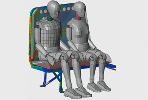
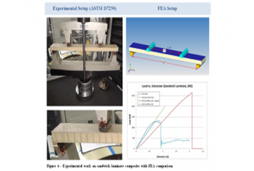
Progressive Ply Failure Simulation of Composite Sandwich Panel – 16g Sled Test
In this 16g LS-DYNA sled test simulation, the focus was the composite sandwich panel bulkhead that supported an attendant seat. The objective was to test the design and keep the project on schedule. One can think of this as FEA insurance; that is, it is must less expensive and faster to virtually test than to destroy prototypes on a 16g sled test.
The LS-DYNA model was constructed from the client’s CATIA geometry. The Nomex cored sandwich panel was idealized using a combination of solid elements for the core and laminate shell elements for the composite skins. This type of 3D modeling provides accurate simulation of the progressive failure of the composite skins (see 026_Jensen,A_PAPER Broad-Spectrum Stress and Vibration Analysis of Large Composite Container.pdf). Likewise, phenolic anchor blocks were modeled with solid elements and then integrated into the wall panel. As part of the virtual manufacturing process, key fasteners were preloaded prior to analysis to enable shear transfer across bolted interfaces.
The model was first proof tested without the ATD using LS-DYNA’s implicit solver to ensure that the structure was tight and could withstand the 16g sled test environment. After this verification stage, the model was repurposed with an ATD for the full, nonlinear, transient explicit analysis. At the start of the transient analysis, bolts were preloaded and the ATD was allowed to settle onto the attendant’s seat, once the model had stabilized, the sled’s deceleration pulse was applied. Progressive composite failure was simulated using *MAT_54 with strain based failure criteria for tension, compression and shear. All metal components strength levels were based on MMPDS values. The complete transient, nonlinear simulation took about four hours to solve using 16 CPU-Cores. Results aligned well with the 16g sled test data.
60 MPH Sled Test of Heavy Cargo Strapped to Aluminum Pallet
An unusual name for this project to provide a bit of mystery as to what we were actually doing. Although we have done several consulting projects that involved the idealization of cargo straps into FEA models employing shell elements for the fabric and beam elements for the connecting hardware (loops, hooks, D-Rings, etc.), this project was even more complex since the straps were pre-tensioned to set tension loads prior to the 60 MPH test. Just to make more interesting, the cargo of interest was placed on top of an polyurethane mat that covered the aluminum pallet. The material list for this model then included: fabric, rubber, aluminum and steel and all extended into their respective nonlinear ranges. As for the modeling process, simply wrapping the straps around the cargo required a separate analysis with the final strap configuration (displacements) morphed onto the final model for pre-tensioning. The transient sled test was the easy part. Results from this work were used to assure our client that their cargo would stay put on the sled and not fly off into space causing some sort of unspecified serious damage.
Drop-Test Analysis of Circulation Chest Compression Device
This was just your standard drop-test analysis of first-responder hand-carried medical device. Since it used an exoskeleton of PC / ABS molded components around various electronics and a heavy battery pack, our client was a bit nervous about whether it would survive a drop from four (4) feet. This is the type of FEA nonlinear consulting that Predictive Engineering has been doing for about 20 years and really presented a very little challenge. The polycarbonate (PC) and acrylonitrile butadiene styrene (ABS) blend was modeled as an engineering plastic with a yield strain of 4% (Bayblend FR3010). The model was idealized using shell elements for plastic molded parts and solid elements for the thicker elastomeric corner protective “bumpers”. The model was then dropped on its four corners and then front and back. Results suggested several design improvements to prevent corner damage and also internal damage at the battery mounts.
Extension Spring Controlled Medical Device for Dental Delivery Systems
Extension springs are well-known mechanical devices that can be ordered with specific tensile preloads. From a modeling perspective, they represent a very interesting nonlinear response and if the spring is bent or twisted, then its contact behavior becomes of importance in its mechanical response. Our client came to us based on our experience in prior projects, although they have in-house FEA capabilities, the complexity of this project merited out-sourcing. The simulation of the extension spring was done via LS-DYNA’s *INTERFACE_SPRINGBACK_LSDYNA keyword command. A FEA model of the extension spring was made using beam elements and then stretched. When the desired preload was reached, the analysis was stopped and the beam stresses dumped out into dynain file via the _SPRINGBACK keyword. This file was then stripped down to just the *INITIAL_STRESS_BEAM results and used as an *INCLUDE file in the full FEA model of the medical device. In the full analysis, the device was built up using rigid bodies to capture its swing motion with the only deformable parts being the beam elements used to model the extension spring. Results were validated against the client’s experimental data and was found to be spot-on. With this validation, the spring stresses could be interrogated with high confidence and used to improve the fatigue life of the device.
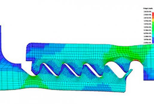
ASME Suitability Assessment of Evaporator Vessel for Complete Flooding
Our client had several evaporative vessels in service, that over the years had accumulated sufficient shell side residue that was hindering their efficiency. Given that the tube bundle section of the vessel was 30 m long and 4 m in diameter, the only economical manner to clean out the residue was determined to flood the vessels. The challenge was these vessels were never designed to be flooded and, without some sort of documentation or design modification, the only alternative would be to scrap the vessels and install new multi-million dollar evaporators. Through several rounds of finite element analysis (FEA) it was determined that the vessel would fail upon being flooded. At this stage, in collaboration with our client, it was determined that the lower tube sheet could be supported and with some minor reinforcements (e.g., nozzle repads), the vessel could be flooded and still fully comply with ASME Division 2, Section VIII specifications. The tubesheet support involved cross-bracing the bottom of the tubesheet using nonlinear contact between the support and tubesheet. It should be mentioned that the vessel was found to comply only via the plastic collapse section of the ASME code. To verify that the design would be robust, the hydrostatic pressure load was ramped up to 3x its flooded state, exceeding ASME’s requirement of 2.4x. For conservativeness, the material law assumed perfectly elastic-plastic behavior. At the end of this analysis, our client was confident that the vessel could be flooded and work is underway to build the support structure and then proceed with the cleaning operation thereby saving their company millions of dollars.
Nonlinear Load-Limit Analysis of Plastic Rebar Support Structure
A injection molding company was in the process of designing a new rebar support seat for its end client. Given that the production volume would be in the hundreds and thousands of pieces, it seemed reasonable to obtain some FEA anti-failure insurance. The non linear FEA modeling was necessary given the material’s nonlinear elastic response and the use of snap-fit joint between the base and upper chair segments. The modeling (FEMAP) was quite simple using client supplied geometry and then using a mixed mesh approach of hex elements in the snap-fit regions and then a tet mesh in regions of lessor interest. Mesh transition was done using _TIED contact and verified by turning off the grid outlines and looking for a smooth stress transition between the meshes. Results indicated that the design needed significant revision to achieve the client’s load requirements to prevent premature snap through and collapse of the seat.
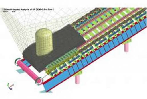
Simulation of the Comminution Mechanics of High-Speed Cone Crushers
This project leveraged several key skills sets within our consulting services: (i) fracture mechanics; (ii) comminution expertise from +10 years at the U.S. Bureau of Mines; (iii) idealization of complex structures into predictive numerical models; and (iv) importantly, +20 years of LS-DYNA experience through hundreds of consulting projects. This project started with the premise that we could use the discrete element method (DEM) to model the comminution of the rocks. After a few pilot models, we determined that to capture the correct stiffness and stochastic characteristics of rock fracture, the time step for the analysis would be too small for practical engineering work. We then switched to modeling the rocks using standard Lagrangian elements but with a twist. The twist is that LS-DYNA *MAT_24 material law allows the user to define a stochastic variation of the elastic modulus, yield stress and plastic strain (among others). By setting realistic ranges for these parameters, rock fracture could be simulated that matched well with the Bond Work Index. With this calibrated virtual rock pile, a series of comminution studies were carried out on a high-speed cone crusher. The kinematics of the cone crusher were fully represented using rigid bodies. With this configuration, rocks were crushes while measuring crushing efficiency via top frame bounce and amperage draw (horsepower (HP)). Results from the model correlated well with in-field measurements of cone crusher power draw, final rock sizing and wear patterns on the liners. Although the model is highly nonlinear, run times were nominal given that the only deformable bodies in the model were the rocks while the cone crusher parts were rigid bodies, albeit providing contact to the rock parts and torque outputs on the main drive.
Impact Analysis of Polymeric Additive Manufactured Lattice Structures
This work was sponsored by the US Army’s Natick Soldier Systems Center to investigate additively manufactured lattice structures for improved blunt impact protection for helmets. The idea is simple enough, modern helmets are designed to deflect or mitigate the impact forces due to bullets (high velocity) but not so much for blunt force impacts (lower velocity). In military operations, blunt force impacts are common, albeit sometimes accidently, due to falls or in the rush to enter-exit buildings and vehicles. In combat, flying debris also present challenges to helmet designers where the impacts can be both high- and low-velocity. Our work was to set the foundation for the exploration of polymeric 3D lattice structures to create the next generation of energy-absorbing helmet liners for military applications. Current foam liners, whether multi-layer or sculptured, all exhibit more-or-less the same energy-absorbing response which is fine for high-energy impacts but lacks the sensitivity for low-energy impacts. If one can move away from the use of foam and toward that of a 3D polymeric lattice structures, then it should be possible to engineer a helmet liner to have a more variable or tailored energy-absorbing response. To create such structures, the additive manufacturing process was used. The first phase of this test program was to develop a validated FEA model that could be used to predict the impact response of additive manufactured 3D lattice structures. The additive material used for the lattice structure was a methacrylate photopolymer. Standard static compression, tension and bulk modulus testing was performed on 20 mm thick blocks. The same samples along were subjected to impact testing at various strain rates. The static and dynamic data was then fitted onto a series of strain-rate dependent curves. The final *MAT_181 law was then validated against these same coupon tests and shown to have good agreement. This material law was then applied to a 3D lattice model for virtual impact testing. Unfortunately the full-on lattice simulations showed no correlation between FEA and test. Although the material law development was accurate to the coupons and the FE model was verified to other numerical tests, it was reasoned that the material characterization had radically changed from large sample (centimeters) to lattice structure (millimeters). Although this project was a spectacular failure, it did advance our understanding about the challenges of modeling polymeric additive materials. Moving forward, we will be working on a new suite of mechanical tests that would be scale specific to lattice structures… but that will be next year’s conference paper.
Real-Time Durability Analysis of Bus Seats
A core challenge to any finite element analysis (FEA) is figuring out loads and how to apply them. For static events, it is usually straightforward. In the case of durability testing, loads are obtained from accelerometers mounted on test vehicles that are driven for hours, if not days on test tracks or routes that hopefully replicate the most severe road conditions possible. These accelerations can then be numerically processed and used for various frequency domain analyses such as a random vibration analysis (i.e., PSD), a frequency response analysis, or steady state dynamics. Although powerful and useful, these solution sequences are all based on the linear normal modes response and do not account for the nonlinear evolution of the structure as it shakes, rattles and rolls. As for a nonlinear material response, forget about it. Our approach is to describe how one can take the full acceleration time history and with little sacrifice in accuracy, perform a nonlinear, transient dynamic implicit analysis over a time span of 5 to 10 seconds. The reason for choosing implicit analysis is based on two factors: (i) the necessity for finely detailed meshes in regions of high-stress, and (ii) quick solution times. A series of bus seats was analyzed using this technique and showed good validation against test track data. From a simulation viewpoint, this work could have been accomplished without the use of the implicit solver since run times were in hours whereas trial explicit runs indicated run times in days on equivalent hardware running with 32 CPU-cores.
Implicit Failure Analysis of Seismic Restraint Brackets
Vibration is the enemy of high-resolution scanning electron microscopes and great lengths are taken to prevent ground motion from being transferred to the equipment. Placing the equipment on a massive isolator-mounted table is effective is preventing vibrations from effecting SEM results but then requires restraints to prevents excessive motion during a seismic event. The objective of this analysis was to ensure that the restraint brackets meet seismic requirements of SEMI-S2 (UBC 1997) and the International Building Code (IBC), and evaluate the bolt and anchor strength per HILTI guidelines. A finite element analysis model was constructed and analyzed to determine the bolt forces and the ultimate load of the brackets. The results from this analysis work allowed the customer to choose an appropriate material for the brackets and size the bolts and anchors.
Blast Analysis of Large Generator Housings
LS-DYNA Nonlinear FEA consulting services, training and sales have been an integral part of Predictive Engineering for more than 15 years. In recent project work, we investigated the blast resistance of several large generator housings. The blast pulse was determined by ConWep calculations given the TNT charges and distances from the housings. Although LS-DYNA has several built-in methods for simulating blast loading (e.g., *LOAD_BLAST_ENHANCED and *PARTICLE_BLAST), most far-field air blast load calculations of exposed structures can be done as shown in the graphics below. Results from this investigation allowed our client to decrease the weight of their design to such an extent, that analysis costs were easily recovered and that the housings would meet all infrastructure protection requirements at the base.
Dynamic Analysis of Plastic Transmission Shifter Assembly
When a local manufacturer of off-road vehicle accessories was tasked with developing a new drivetrain technology for a large automobile manufacturer, the need for FEA structural analysis was apparent. The product is a Center Axle Disconnect (CAD), which is responsible for a vehicle’s transition between four-wheel drive and two-wheel drive. One of the major concerns with the design is the repeated impacts between metal and plastic components. The disconnect shifting at very high speeds results in high impact situations. With these impacts, durability is a critical concern. Using LS-DYNA, the impact events were analyzed as fully transient-dynamic events. Impact velocity was calculated via conservation of energy based on the transmission spring preload. This was applied to the FE model as an initial velocity and the analysis started just before impact. Not only did the non linear fem analysis results provide stress values for the components during the impact event, but also real-time visualizations of the transmission components impacting, sliding and rotating through the travel. This analysis work helped guide the design of rubber O-rings that allowed the transmission to operate at high speeds while reducing stress on the plastic components.
Composite Stiffener Insert Analysis for Sporting Equipment
Carbon fiber composite materials are continuing to see increased usage in sporting equipment: helmets, fly rods, bike frames, golf clubs, protective gear, hockey sticks and skis just to name a few applications. While the high strength-to-weight ratio is the main appeal of carbon fiber laminates, they also provide the ability to adjust stiffness characteristics by modifying the fiber orientation, ply thickness and number of plies. This was the focus of a recent LS-DYNA consulting service project with a major sporting equipment manufacturer designing a shoe with a carbon fiber sole. While the product needed to be light weight and capable of large deflections, it was important to fine tune the stiffness of the sole under different loading conditions. Before exploring new designs, an existing prototype was subjected to several laboratory tests. These tests were recreated using LS-DYNA and simulation incorporated the full nonlinear behavior of the sliding contact between the shoe plate and the test fixtures. LS-DYNA’s MAT_54 material model allowed the mechanical properties of composite to be calibrated to test data before being used as predictive model for potential designs. Working with this simulation software allowed the client to perform virtual testing on multiple geometries and layups without generating physical prototypes.
Cargo Net Nonlinear FEM Analysis Under Flight (1.25g) and Emergency Landing (9g) Loading Conditions
Cargo nets are extremely useful mechanical devices to securing loose items or bulk cargo during flight. Interesting enough, how one designs the net can greatly influence how load is transferred from the net’s webbing into the aircraft’s anchor points. The client chose Predictive based on our prior FEA consulting service work using cargo nets to tie down boxed cargo onto aircraft shipping pallets. In this project, the client was responsible for the design of the cargo net attachment points onto the aircraft’s frame. Ideally, we wanted to ensure that the loads were as close as possible to be evenly distributed. That is, if the cargo net had 12 attachment points, the goal was to have each frame attachment point bear 1/12th the load. In practice, this was very difficult to achieve given the net’s dynamics during flight and emergency landing. The loose cargo tended to accumulate near the floor of the aircraft, putting higher load on the floor anchors as versed the roof anchors. The complexity of the FEA work was due to the nonlinear stretch and deformation of the polyester webbing and how the cargo net would deform to accommodate the bulk profile of the cargo. The transport plane used a combination of nets and each net was optimized to achieve as nearly as possible uniform anchor loads. Since the Federal Aviation Administration (FAA) prefers that emergency landing load analysis be performed statically, the cargo net analysis was run using the implicit solver within LS-DYNA. From start-to-finish, we were able to reduce single-anchor reaction loads by approximately 50% by careful redesign of the webbing pattern.
FEA Residual Stress Analysis in Brazed Ceramic-Metal Structures
This work represents the culmination of perhaps a decade of FEA simulation work for this client. After years of performing “good-enough” simulations of the braze process, Predictive Engineering was given the opportunity to do a top-to-bottom complete nonlinear simulation of the braze process. The model was exercised from room temperature up to the braze material’s eutectic melting point around 700C and then back down to room temperature. Metallic and braze materials used temperature dependent elastic modulus, yield stress and CTE values. For example, at 700C, the braze material has a very low elastic modulus and its yield stress is near zero since the braze has recently solidify. On the metal side (titanium or stainless steel), the modulus, yield strengths and CTE’s do vary as the structure cools to room temperature and were incorporated into the FE model. The ceramic materials (alumina or zirconia) are basically inert within the temperature range of interest. The braze and metallic materials were simulated using a specialized material formulation (*MAT_188: *MAT_THERMO_ELASTO_VISCOPLASTIC_CREEP) which allowed for temperature dependent mechanical and thermal properties. The braze layer was inserted in-between the ceramic and metal components using tied contact since each component used a different mesh density. The final model was then analyzed using the implicit solver within LS-DYNA MPP Double-Precision. At room temperature, the residual stress prediction aligned reasonably with prior work albeit with lower stresses. The ability to more accurately capture the physics of the problem was very useful to the engineering team since some occasional failures of the ceramic-metal components had been noted and could be directly ruled-out since the FE model showed that the residual stresses were not driving the failures. In the modeling world, knowing what you know with greater confidence is an extremely useful piece of information. Additional FEA consulting is planned to investigate other geometries and explore different braze geometries.
Thermal-Growth and Compression Analysis of High-Vacuum O-Ring Seal
Compression and the resultant sealing action of O-rings is something that Predictive Engineering has done many times over the years as a FEA consulting service. A unique twist to this project was that our client was seeing unexpected component breakage during the bake-off process of their system. That is, to drive off organics and prepare the system for high-vacuum usage, the machine would be heated up to 200C. Upon cooling to room temperature, our client would notice the intermittent loss of vacuum within the system. Not in every machine but enough that it had to be chased down and fixed. A FEA model was then built of the component structures surrounding the O-ring. An advantage of their system was that axisymmetry could be leveraged. In normal operation, the O-ring would fill its respective cavity and create more than sufficient sealing pressure. We then added a thermal load to the model and noticed that the O-ring would grow significantly and create extreme pressures against the sealing components. This was our smoking gun that was causing the failures. With a redesign of the O-ring cavity, the system performed as designed. As an analysis note, the model was run in implicit mode using LS-DYNA MPP Double-Precision and took about 5 minutes to achieve “normal termination.”
Impact Analysis of Earth-Tilling Ripper Point
Our client wanted to understand the ultimate impact characteristics of their new ripper point design. In field experiments, they had experienced point breakage when the ripper point had impacted large rocks during field tilling operations. Although the point is spring loaded, the impact was severe enough to break off the wing edges. The ripper point material was a carbidic austempered ductile iron (ADI) and although it possess favorable wear characteristics, its toughness is quite low. Ideally, the designers hoped that ripper point failure could be prevented by using a low-strength shear bolt but this proved troublesome. Given the low-speed of the impact event, the analysis was run using the implicit solver within LS-DYNA. Failure loads were determined by slowly loading the point based on assumed rock impact angles (direct and angled). Once element erosion started to occur, the ripper point would fail catastrophically. Recommendations from this included a redesign of the ripper point and the use of a smaller diameter shear bolt within the spring-loaded system. Material optimization was also discussed since the use of carbidic ADI can be challenging given its low toughness.
Durability Analysis of Automotive Tie-Rod
A durability analysis was performed of an automotive front-upper tie rod. This is about as simple as it can get except for their requirement to access the low-cycle fatigue life of the tie rod. Within the automotive world, it is common to bracket the performance of critical parts based on their response to overload conditions and then verify their classic linear load response. In this project, the boundary conditions were variable and required contact to be enforced between the connecting rod and the joint pins since multiple load cases were specified and it was just easier to let the tie rod find its own equilibrium. The material model for the tie rod analysis was based on common forged steel having a minimum yield strength of 420 MPa with an ultimate strength of 515 MPa and 18% plastic strain to failure. However, the client also requested that specialized materials be used for the spacer sleeve & tube and for the eyelet and clevis. Under the low-cycle load cases, extensive plastic deformation was noted in the tie rod and this was expected. The objective was to determine if the tie rod could survive after severe impacts and still return in serviceable condition. Given the material modeling and the interesting nonlinear behavior this LS-DYNA consulting project still provided us with some surprises and challenges.
Stress Analysis of Polyethylene Tank and Pad Assembly
Storage of acids is commonly done in vertical polyethylene tanks. For ease of connections and other storage considerations, a polyethylene pad is provided to keep the outlet nozzle off of the floor and also ensure that the tank settles flat. Our client was interested in assessing their current 5,000 gallon tank given the ASTM D1998 Standard Specification for Polyethylene Upright Storage Tanks. The specification in essence de-rates the polyethylene’s nominal yield stress of 3,800 psi down to 600 psi. However, code interpretation states that this stress is only applicable to the calculation of hoop stresses since its intent is to prevent long-term creep failures. Given this code flexibility we classed the tank vessel to meet the 600 psi hoop stress and then allowed other localized stress concentrations to exceed 3x this value per ASME Section VIII, Division 2 rules. Although the analysis might be considered linear, the tank rests on a hollow pad where the internal structure is a series of hemispherical domes. As the tank is loaded, it pushes down on the top of the pad, which in turns contacts the top surfaces of the domes. Given the complexity of the contacting surfaces and the nonlinear deformation nature of the low elasticity rotomolding crosslinkable polyethylene (E=90,000 psi), the resulting analysis was highly nonlinear. Using the implicit solver in LS-DYNA MPP Double-Precision r8.0.1, the analysis quickly converged and readily scaled using more CPU-Cores. Final results indicated that the tank and pad were well designed for the long term storage of heavy fluids (e.g., specific gravity > 1.8).
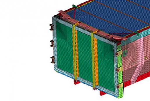
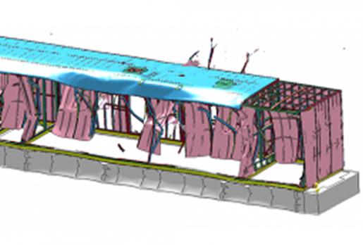
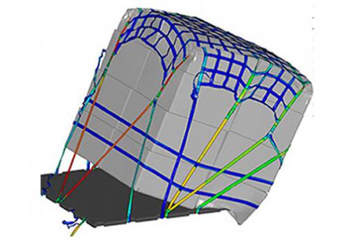
Stress, Vibration and Drop Analysis of Large Composite Transportation Container
This was one of Predictive’s marquee projects and selected results were published in the 14th International LS-DYNA Users Conference “Broad-Spectrum Stress and Vibration Analysis of Large Composite Container.” Using one FE model, we were able to run the complete gauntlet of nonlinear analyses from explosive depressurization CFD calculation to various nonlinear static loads to explicit drop analysis of the fully loaded container. The container used a variety of composite layups from thin to thick solid laminates and whenever possible in larger flat sections, a 25mm thick sandwich laminate. The composite construction was based on glass-plies that were vacuum-infused with a non-flammable resin. The overall container size was 2.5x3.2x10m and was split into bottom and top shells. An aluminum extrusion with an inner O-ring was used to create the closure around the perimeter of the top and bottom shells. The container was seal using a series of latches. To reinforce the composite at strategic loading points, other aluminum structures were implemented. This complete assembly of composite and aluminum components was analyzed under internal and external pressure along with a number lifting and impact loads. Every load case was nonlinear since structural components were preloaded via bolted connections from the closure latches to aluminum reinforcement plates to internal spring mounts. Extensive optimization was done on the composite structures based on experimental data. The composite material information was developed based on the validation of FEA models to test data. Such close linkage allowed greater confidence in the development of composite transition regions between solid laminate and the sandwich regions and of course in the interpretation of composite stress results. Progressive ply failure was an important modeling metric since damage was allowed by the specification but not complete composite failure. Thus the container could be loaded higher than a standard linear composite analysis would allow since some individual ply failures were tolerated.
In many load cases, the model was preload via an implicit analysis and then allowed to impact using the explicit solver within LS-DYNA. The drop tests followed standard procedures for impacts on rigid surfaces. What was unique was also modeling the cargo on a bed of springs based on the manufacturer’s nonlinear force versus deflection curves. It seemed that every simulation skill set was used on this project from CFD to Nonlinear Implicit to extreme nonlinear transient vibration analysis. The container has passed CDR and is now heading into manufacturing.
Nonlinear Stress and Fatigue Analysis of Flexible Driveline Joint
Mechanical couplings for drivelines are as simple as the classic U-Joint or if damping is necessary, one can insert large rubber disks between opposing steel plates or use incompressible fluids (e.g., oil) between opposing blades or with this one client, use a stack of 20+ bolted disks to efficiently transmit torque while allowing for slight mis-alignments between the shafts. It is one of the joys of our work that we see such broad ranges of mechanical systems and we are often amazed at the cleverness of our client’s approach to solving engineering challenges. To meet their high-cycle fatigue requirements, the non linear analysis was run using a nonlinear FEM approach to capture contact between the plates under the bolted regions as torque was applied to the main shaft. Given the large stack-up and the requirement to have the shafts slightly mis-aligned, no symmetry could be exploited and the model ended up having nearly a million DOF. The fatigue model for the material was based on 304 SS and presented its own difficulty given that at millions of cycles the run-out stress can be as low at 70 MPa (10,000 psi). Results from the model showed that the disk pack would pass with margin under the specified axial mis-alignments and as far as we know, as of this writing, is still in service in multiple locations.
Dynamic Analysis of Tensioned Undersea Rope
Modeling the dynamic interaction of vibrating, submerged structures was and continues to be a topic of research. One of the more famous studies was done by R.J. Fritz “The effects of Liquids on the Dynamic Motions of Immersed Solids” in 1972. In our published work (14th International LS-DYNA Users Conference: Interactive Dynamic Analysis of Subsea Lifting Ropes), we show how one can couple the dynamic forces of fluid movement (drag and vortex shedding) to the transient, dynamic response of a submerged high-strength plastic rope. Although rather technical, a user-routine was written that coupled the ropes dynamic movement to the calculation of fluid forces that were then fed back into the model in real time to dampen or excite the ropes dynamic response as it was tensioned and moved through the sea. Although one could do a CFD fluid-structure-interaction (FSI) type simulation with many commercial codes nowadays, the scale of our project was to simulate the behavior of a five kilometer (5 km) long submerged haul rope. To attempt this using a CFD-FSI approach would not quite be possible given that we needed to make hundreds of runs to investigate different loading, sea currents, ship movement and the potential for rope-to-rope tangling during the lift operation. It was fascinating work and showcased the ability to model FSI without necessarily having to tow along a CFD code.
Drop, Crash and Static TriAxial Loading of Jet Engine Stand
If it flies, then most every manufacturer is concerned about minimizing the weight of their design. This LS-DYNA consulting project optimized the structural performance of a metal stand used to transport jet engines between the United States France. A key requirement was to demonstrate that the jet engine would not come flying off the stand and crash into the plane’s cockpit during a 9g crash event. Besides the crash testing, the stand had to withstand a 12” drop along with lateral impact load of 3g (lifting load case). These dynamic loads were then followed by static testing where the stand was pulled, pushed and lifted using a triaxial load set. Lastly, a normal modes analysis was done of the complete assembly to ensure that it would not get excited during ground transport. The FEA analysis work was validated against the 3g lateral load and the most severe triaxial load. With this validation, the client was able to use the simulation results to demonstrate compliance with the other specifications. It should be mentioned that during the course of this investigation and working collaboratively with the client, we were able to reduce the weight of the frame by around 30% while exceeding the mechanical performance of their original stand.
Torque and Snap-Fit Activation of All-Plastic Medical Device
A rather old-style multi-component medical instrument was reengineered into an inexpensive all-plastic device. The design required several stages of movement from activation (a twisting snap-fit motion) and then application (pushing and sliding). Since the design was a one-use application, it didn’t matter if internal components were deformed. Given the highly nonlinear behavior of the system and its dynamic operation during use, LS-DYNA was used to analyze the system.
This LS-DYNA consulting project presented several difficulties due to the variety plastic materials that were required to be modeled from copolyesters, nylon 12, Zylex 20% filled to three different grades of polypropylene. The snap-fit behavior was perhaps the most challenging since plastic-against-plastic contact becomes quite sticky at higher contact pressures. An integral part of this device was an o-ring seal. The seal was modeled using a basic rubber material law and the simulation work was used to determine the sealing pressure given various sizes of O-rings.
Given that this device was to be manufactured in the millions, sensitivity and optimization studies were performed. We were able to show the quantitatively how the different grades of plastic could push the operational behavior into statistically unsatisfactory regions and in other studies how our client could use the most inexpensive plastic with no degradation in performance.
At the end of this study, abuse loading was investigated where the device was loaded to its failure point. Plastic material failure was simulated using a combination of tensile, compressive and shear failure data. The LS-DYNA simulation was compared against experimental data and found to be in good agreement.
This LS-DYNA consulting effort let our client decide with confidence on what materials to use, what were the key design features and how the device would behave in normal operation and under abuse loading.
LS-DYNA FEA Simulation of Airplane Seat 16g Sled Test with ATD (Dummy)
The engineering of airplane seats is quite complex due to competing demands for lightness and the ability to survive a 16g sled test. Experimentally, a 50% percentile dummy or anthropomorphic test device (ATD) is strapped into the chair and then subjected to a 16g acceleration pulse with a half-sine pulse width of 0.18 second. The test procedure is well defined under 14 CFR Part 25.562, Amendment 25-64 and JAR Part 25.562 with guidance given under SAE AS8049 Rev. A and for the ATD under 49 CFR 572.
In our work, Predictive constructed a detailed model of the airplane seat within Femap. After some debugging and verification analysis of sub-component models, the FEA structural model was combined with a simplified dummy model (LSTC Hybrid III Adult Fast, 50th percentile male) for the complete test simulation model.
The crash test load consists of the application of a 16g half-sine wave acceleration pulse through it leg supports. The simulation was run for 360 milliseconds with run times of around 45 minutes. Sensitivity runs were performed to assess the effects of mass scaling, hourglass, element formulation, damping, sliding interface energy and contact behavior. Some runs were also made using the double-precision version of LS-DYNA. In all cases the results converged to nominal behavior. At the end of this effort, the client allowed us to view the video of the sled test and everyone was quite excited to see a tight correlation between LS-DYNA model and sled test. Subsequent to this qualitative correlation, the model showed good quantitative correlation to load cell data and noted structural damage in the prototype.
Torque and Nonlinear Buckling Analysis of Surgical Endoscopic Wire-Wound Tube
Robotic endoscopic surgery requires the use of highly engineered steel micro-cables and helical hollow strand (HHS) tubes. The wire tube is the main structural component that allows endoscopic probes to navigate through arterial systems. It must be flexible yet be capable of sustaining high torque loads without buckling. A LS-DYNA model was constructed and correlated to one set of experiment data. Based on these results, two other HHS models were created and shown to correlate directly to the experimental results. This out-of-the-gate correlation demonstrates that FEA modeling can be a predictive tool for the development of the next generation of these tools.
National Institute of Science and Technology (NIST) Investigation of Respirator Fit and Function
This was an in-depth detailed project to study the fit and function of a fireman type respirator mask. LS-DYNA was used to perform the fit study of the mask against a simulated human head. The silicone material model was easy to obtain while that for human tissue required some investigation. The best material model fit for human skin was that of a soft rubber compound within an elastic membrane. A transient flow study within the nose cup of the respirator mask was conducted using CFdesign. Inhalation and expiration studies were conducted using standard respiratory breathing curves. Transient flow results indicated that the standard respirator mask creates some turbulence during inhalation that might cause breathing difficulty. Research papers are in process to elaborate upon these results with a shared co-authorship.
Stress Analysis of Cast and Extruded Aluminum Loading Ramps
Two potential design concepts were investigated. Both concepts used aluminum construction materials and a common side rail but the material strength, design weight and fabrication cost differed.
The investigation started with linear static stress analyses of the two designs under a variety of operational loadings. Once the superior traction grate design had been selected, it was time to test the maximum load carrying capability of the complete ramp assembly. LS DYNA was used to handle the nonlinear nature of this analysis as the material yielded and the structure buckled.
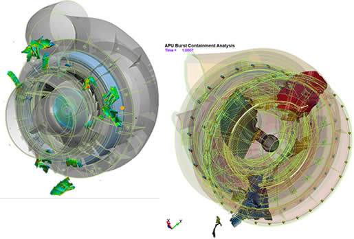
Burst Containment: Aviation, Industrial, Medical and Military
Burst containment testing is challenging and expensive since the test destroys pretty much everything and often times, one has no idea if containment or non-containment was marginal or not.
Transportation Analysis -Keeping Things “In-Their-Place” Whether Over Land, Sea, Air or Space
Welcome to our overview of Predictive Engineering’s FEA nonlinear consulting services for transportation simulation. Over the years we have analyzed the transport of cargo, jet engines, pressure vessels, humans (anthropomorphic test devices or ATD’s), comp
Predictive Engineering LS-DYNA DEM and SPH Simulation Project Work
DEM and SPH are both visualized as small discrete spheres but that is about all they have in common since DEM is often used for modeling discrete particles such as rocks or pea pods while SPH is used for modeling continua such as fluids and solids.
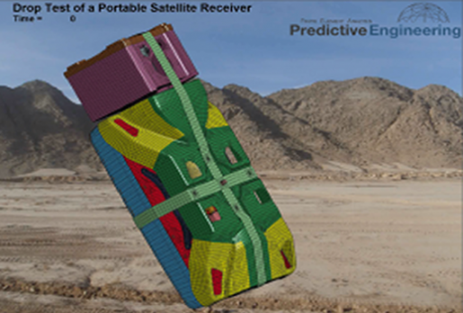
LS-DYNA FEA Simulation of Drop Test per MIL-STD 810e of Carbon and Kevlar Composite Electronic Device
.Introduction: An advanced electronic device with a composite protective shell of carbon fiber, kevlar and standard fiberglass was drop tested using LS-DYNA. The drop test procedure followed that as given by a MIL-SPEC 810e sequence of 26

Impact Analysis of Additive Manufactured Lattice Structures
The idea is simple enough, modern helmets are designed to deflect or mitigate the impact forces due to bullets (high velocity) but not so much for blunt force impacts (lower velocity). In military operations, blunt force impacts are common, albeit sometime
Capturing Pin-Ejection in Drop-Tower Tests of Digger Tooth Systems
This simulation provided the first true glimpse of the completely transient impact behavior of digger-tooth system. The point (the digging part) is attached to the nose (interior supporting part) by deceptively simple arrangement of steel and rubber pins.
Drop Test Analysis of Large Nuclear Waste Storage Containers
As the weight of the container increases, the drop height decreases. As an example, a 50,000 lbf container must survive a drop from 12" onto its most vulnerable corner.
Blast Analysis of Large Generator Housing
CAD geometry of the generator housing was idealized into a quad-dominate shell FEA model. The housing is a space-frame structure composed of structural steel tubing.
Impact and Fracture Mechanics Assessment of a Fused Silica Window
A finite element (FE) solid model of a 18” diameter, 1.5” thick disk was constructed based on information provided by the engineering team at Arnolds AFB (see Appendix).
Extreme Implicit Nonlinear Analysis of Plastic Thread Design
Since the company had experimental data which strongly indicated a failure load of 2x the design load, there was a whirlwind of debate as to whether to proceed to mass production or conduct an extensive redesign campaign.
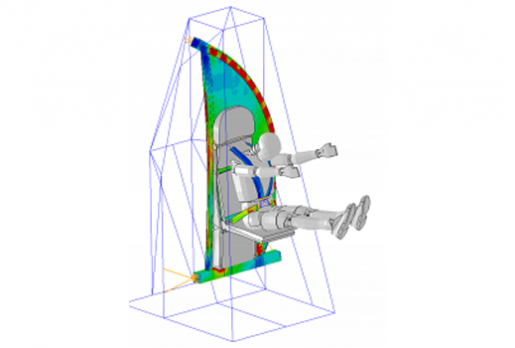
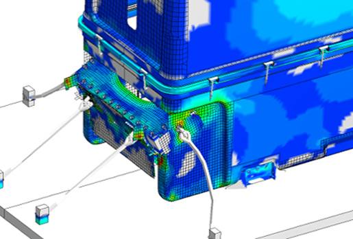
16g Sled Test Analysis of Lavatory Wall with Attendant's Seat
In this LS-DYNA FEA consulting services work, the objective was to limit the design and schedule exposure of a new design.
Cargo Net Simulation - Nonlinear FEA Consulting
In the military world, aircraft often carry both cargo and personnel and the last thing that one wants is for the cargo net to break and have cargo flying around inside the aircraft during a severe landing event (that is to say during a crash landing). To e
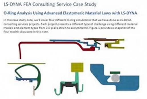
O-Ring Analysis Using Advanced Elastomeric Material Laws with LS-DYNA
The analysis of O-rings has historically been difficult since the modeling process involves large displacement and large nonlinear strains couple to multi-body contact between the O-ring, its gland cavity and the mating part.

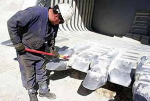
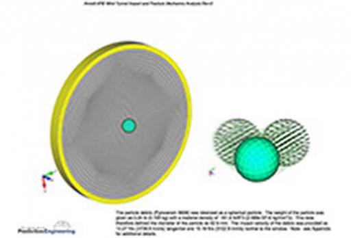
LS-DYNA Discrete Element Method Analysis for Load Analysis of Mining Dump Truck Body
The discrete element method was used to simulate the load carrying capacity of a mining dump truck body. The LS-DYNA analysis investigated the stress response of the dump truck body during the shovel drop of a rock load.
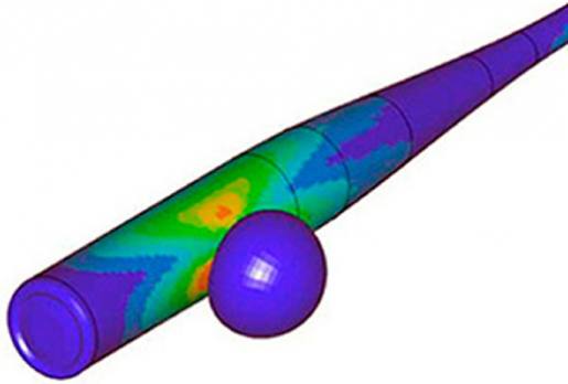
Baseball Bat Mechanics
Modeling Assumptions and Details: A FEA model was constructed of an aluminum bat based on geometric and material property data supplied by the client. The model was validated by weight and modal analysis.
Structural and Impact Analysis of Large Composite Container
Composite Analysis from Static to Impact to Transient Dynamic with LS-DYNA
LS-DYNA is well known in the automotive world for its ability to simulate extreme nonlinear transient events such as car crashes.