CFD Investigation of Pressure Drop and Fluid Force Through Relief Gate
Analysis
Objective
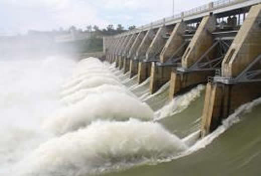
This CFD consulting investigation was performed during the design process of a water control gate for a large water reservoir system in the northwest. A general volumetric flow rate for the gate was given and the designers needed to be sure that the pressure drop across the gate did not exceed project allowables. Given the constricted nature of the relief gate, a CFD analysis was the only logical approach. In addition to the pressure drop requirements, it was important to determine the CFD deriveforce on the gate for the structural design of the system. Our CFD services allowed our client to quickly assess whether or not their design would work.
Starting with CAD provided by the client, the geometry was split along the symmetry plane, the area of concern was isolated and small details were removed to facilitate a clean CFD analysis. As CFD consultants to this project, our goal was to ensure a high-accuracy analysis in the minimum amount of time - this means clean CFD-type geometry. (see Figure 1).
Although geometry of the structure was provided, it was up to the analyst to create a clean and efficient solid to represent the computation fluid dynamicss fluid volume (see Figure 2).
With CFD boundary conditions set on the inlet, outlet, and symmetry plane, the CFD simulation was ready to run. Although setup was quite straightforward, significant time was dedicated to interrogating the results from the simulation. This is normal in CFD consulting and the generation of full-field descriptive images is one of our strengths as CFD consultants. Once the CFD model was checked and there was confidence in the results, the client was provided with pressure drop and force values as well as contours of fluid velocity and static pressure (see Figure 3).
Another example of our CFD consulting work is "Stress Analysis of a Movable Deflection Wall in a Coastal Airport Environment"
Keywords: CFD, CFdesign, AutoDesk Simulation CFD, Computational Fluid Dynamics, Fluid Mechanics, Fluid flow, FSI, incompressible flow, pressure drop, fluid pressure, volumetric flow rate, Femap, geometry preparation, CAD de-featuring
PDF Download


