FEA Consulting Services
FEA Consulting Engineers
Predictive Engineering brings to bear more than 20 years of finite element analysis FEA consulting experience in solving the most difficult mechanical engineering analysis challenges.
Our FEA consulting engineers have direct and validated experience in detailed stress analysis, linear dynamics (normal modes, sin sweep, PSD or seismic analysis), ASME Section VIII, Div. 2 pressure vessel analysis from heat exchangers to NQA-1 nuclear and likewise, from construction to transportation, nonlinear contact analysis for complicated assemblies and plastic thread design, high-power transmissions and gear assemblies, off-shore oil patch winches, top drives, and many other fields.
We have also been active in the renewable energy field with complete mechanical stress and dynamic analysis of wind turbine systems, solar panels and photovoltaic systems. We live and breathe FEA analysis and our experience has been earned the hard way by having our models validated in test and in service for over 20 years.
Our work portfolio ranges from deep-diving submarines to large motor home chassis analysis to USAF satellites. The only commonality in our FEA consulting work is that every project has passed our clients’ requirements with flying colors. Contact us to discuss your project.
Stress, Vibration and Fatigue Analysis of Large Aggregate Vibratory Screen
Predictive Engineering has decades of validated experience in the analysis of vibratory equipment. It is one of our key strengths for our FEA consulting services. This analysis was for a very large vibratory screen being driven my multiple rotating shafts. Given the sizing of the screen, a fatigue failure in the field would be extremely costly and hence, a detailed stress analysis was deemed “value added”. The analysis procedure consisted of a normal modes analysis followed by a nonlinear, transient dynamic stress analysis. A standard modal superposition analysis was not possible given the mechanics of the counterweight drives creating a constant radial force in 360 degrees. Our engineering report provided our client with a complete analysis of bolt margins, stress margins are welded joints per ASME weld factors and of course, fatigue service life prediction. How do we know our work is right? All prior vibratory screens that we have analyzed for this client are in-service with no structural or fatigue issues.
Elevator Shaft Assessment for Stress and Fatigue Life
Due to critical safety requirements per ASME A17.1 / CSA B44, stress and fatigue analysis takes on an usual significance for manufacturers of elevator equipment. Our stress analysis services were tasked to perform a detailed stress analysis of a novel elevator motor shaft with attention to stress concentrations created at radii and transition zones at brake pads and the motor engagement keyway. To ensure the highest accuracy, an “old-school” stress engineering trick was used where the surface of the solid mesh was skinned with paper-thin membrane elements. Since displacements are first order FE data, surface displacements from the solid mesh are used to calculate the strains in the membrane elements and lastly, generating more precise surface stresses. Such a technique yielded higher confidence in the stress results and the downstream fatigue analysis.
Seismic FEA of Medical Chiller Cabinets
Medical facilities rely on uninterrupted cooling for critical diagnostic equipment, making seismic resilience a top priority. We provided FEA engineering support to evaluate the seismic performance of large-scale medical chillers under ASCE/SEI 7-22 Minimum Design Loads and Associated Criteria for Buildings and Other Structures. Utilizing finite element structural analysis, our team simulated the response of the chiller cabinets and internal components to horizontal and vertical seismic accelerations. As experienced FEA consultants, we identified key areas for reinforcement, allowing the client to achieve full seismic certification and ensure the reliable operation of their medical cooling systems during seismic events.
Structural FEA of Pedestrian Signal Extenders
Designing reliable infrastructure for transportation systems requires careful evaluation of environmental and operational loads. In this project, finite element simulations were used to analyze a pedestrian signal extender bracket subjected to high wind loads and physical impacts. Our FEA simulation focused on determining the maximum deflection and localized stress concentrations at the mounting interfaces. By leveraging our FEA consulting engineers, the client was able to optimize the geometry of the extender, reducing material costs while maintaining the strict safety factors required for municipal transportation hardware.
Finite Element Analysis of Transportable ISO Container Modules
Transportable power systems housed in modified ISO containers must withstand severe logistical and environmental stresses. We performed comprehensive finite element analysis mechanical engineering evaluations on custom ISO container modules to verify their structural integrity under lifting, transportation, and environmental loading conditions. The finite element analysis evaluated the primary frame, customized cutouts, and reinforced lifting points. Our FEA services confirmed that the modified containers would meet international shipping standards, providing the client with the confidence to deploy their modular power systems globally.
Lift Point FEA Stress Analysis of Energy Modules
The safe handling of massive energy modules requires precision engineering at the lifting interfaces. Our team was contracted to perform a detailed FEA stress analysis on the lift points and supporting structural framework of large-scale modular energy plants. Utilizing advanced finite element modeling, we evaluated the rigging configurations and dynamic amplification factors associated with crane operations. As a trusted FEA expert, we delivered critical insights into the load distribution, ensuring the structural steel framing and lift lugs possessed adequate safety margins for safe hoisting and installation at the project site.
Stress Analysis of Biopaq ICX Three-Phase Separators
Advanced anaerobic wastewater treatment systems rely on robust internal structures to effectively manage gas, liquid, and solid phases. For this project, our FEA engineers conducted a detailed finite element stress analysis on a Biopaq ICX three-phase separator assembly. The finite element modeling evaluated the complex hydrostatic and hydrodynamic loading conditions experienced during continuous operation. By utilizing our comprehensive FEA consulting services, the client was able to validate the structural integrity of the separator internals, ensuring long-term reliability and optimizing the design for the demanding environmental engineering sector.
Dynamic Vibration Analysis of Water Storage Tank
Large-scale water storage tanks can be susceptible to harmonic excitation and flow-induced vibrations during filling and draining cycles. We provided FEA engineering services to perform a dynamic vibration analysis of a specialized water storage tank. Our FEA consultants utilized finite element structural analysis to determine the tank's natural frequencies and evaluate the impact of structural rib placement on mitigating operational resonance. Through this dynamic force analysis and FEA simulation, we delivered optimized stiffening recommendations, ensuring the tank's operational stability and extending its service life.
Seismic and Transient Thermal-Stress Analysis of Heat Exchanger
Critical thermal management systems, such as custom heat exchangers, must maintain structural integrity under both rapid temperature fluctuations and extreme environmental events. For this project, our FEA engineering team conducted a comprehensive seismic and transient thermal-stress analysis of a specialized heat exchanger unit. Utilizing thermal FEA and finite element structural analysis, we evaluated the equipment's response to dynamic earthquake loads combined with severe time-dependent thermal gradients. Our FEA consulting services ensured the heat exchanger met all rigorous safety codes, providing the client with a resilient design optimized for reliable performance in demanding industrial applications.
Virtual Prototyping of Vibratory Rock Conveyor System
Vibration analysis is a key expertise at Predictive. We have been providing FEA engineering services in the analysis of all types of vibratory equipment for conveying, feeding, screening, elevating of bulk products for the mining, food, chemical, medical industries. Our client had decades of experience in building vibratory rock conveyor systems and looked to our FEA vibration specialists to provide “design insurance” to their new vibratory conveyor system. Most conveyor systems will use a standard dual-shaft system that creates a basic sin-wave force loading that can be easily solved using a modal frequency analysis approach. In this case, the loading was based on a 360 oscillation and required a transient, nonlinear analysis. Results aligned closely with our client’s expectations. Stress results were interrogated to determine the machine’s fatigue life and shown to pass. The vibratory conveyor is operating today with no problems.
e-VTOL Electric Motor Stress, Vibration (PSD) and Fatigue Analysis
A major player in the hybrid e-VTOL taxi business (aka Urban Mobility) has been working with Predictive’s FEA engineering consultants to virtually prototype their new e-VTOL inverter motor design that combines lightweight composite components integrated into an aluminum chassis with PCB electronics and then the shaft and bearing components. The complete motor system was evaluated for PCB IC component lead fatigue based on Steinberg’s 3-sigma approach; structural fatigue failure based on MMPDS (MIL-HDBK-5) Specification. The aerospace company was able to successfully demonstrate to their internal team that their new inverter motor design was robust and capable of at least a 100,000 hr service life.
Heat Exchanger Design and Analysis
This project leveraged advanced FEA consulting services to redesign a modular system for heat exchanger units and evaluate their structural and thermal performance under operational loads. The finite element analysis mechanical engineering approach included thermal FEA and finite element structural analysis, identifying areas for improvement, such as increasing wall thickness to reduce stress concentrations.
Heat transfer analysis for multiple configurations was performed using finite element simulations, and results were extrapolated to estimate performance for a full-scale system. The updated design optimized manufacturability and achieved enhanced operational reliability, showcasing the value of FEA engineers in solving complex design challenges.
Dynamic Vibration Analysis of Water Storage Tank
This study used finite element structural analysis to evaluate the impact of rib placement on the natural frequencies of a water tank. The goal was to mitigate vibration during filling by addressing frequency alignment with excitation forces.
The analysis, conducted by expert FEA consultants, revealed that rib placement at mid-level significantly improved performance at higher fill levels, while placement at one-third height provided more balanced frequency increases at lower levels. These findings underscore the importance of FEA engineering and dynamic force analysis in optimizing structural modifications to reduce vibration effectively.
Briquette Stacking Evaluation
This project involved FEA consulting services to evaluate the structural integrity and load-bearing capacity of briquette packs under various operational conditions. FEA engineers conducted a finite element stress analysis to simulate three scenarios: stacking up to six pallets, assessing forklift load impact, and handling full packs with a box clamp attachment. The finite element modeling revealed that the maximum stress during stacking and handling remained within safe limits, ensuring structural stability. However, forklift traversal caused stress levels to exceed the allowable limits, highlighting potential risks under operational conditions. This finite element structural analysis provided actionable recommendations to enhance handling and storage safety, underscoring the value of FEA services in optimizing industrial processes.
FEA of Transportation Modules
This project utilized finite element simulations to analyze the mechanical integrity of data center modules during cargo and caster transportation. The evaluation, performed by experienced FEA consultants, involved doubling the load conditions specified by transportation safety standards and conducting a finite element structural analysis under these scenarios.
The FEA simulation confirmed that the modules remained within elastic stress limits under all loading conditions, with longitudinal bracing significantly improving safety. The study also included a dynamic force analysis for caster transportation, ensuring the modules could endure operational stresses without permanent deformation. These findings validated the modules' structural resilience and highlighted the effectiveness of FEA consulting engineers in ensuring compliance with transportation safety requirements.
Advanced Geodesic Dome Analysis with Nonlinear FEA and Advanced Materials
Discover cutting-edge solutions with Predictive Engineering, Inc.'s expertise in structural analysis and material evaluation. Our recent project demonstrates the integration of updated material properties into a geodesic dome's design, ensuring optimal performance and reliability. This project involved a detailed finite element analysis (FEA) of a geodesic dome structure to evaluate the performance of newly tested carbon fiber materials. Using advanced Finite Element Analysis (FEA) techniques, we evaluated the structure under various load conditions, including resting on supports, suspension, and wind resistance.
With precise modeling and detailed stress and deflection analyses, we validated material safety and compliance, confirming the design’s ability to withstand critical forces. Whether for innovative architectural designs or complex engineering challenges, our FEA consulting and structural analysis services deliver high-performance solutions tailored to your needs.
Fatigue Analysis of Elevator Lifting System
Although FEA is often performed internally within manufacturers of lifting machinery (e.g., elevators, platform lifts, cranes, mobile lifting platforms, and forklifts), FEA engineering is still a specialty where one’s expertise improves with each analysis. At Predictive Engineering, our team has decades of experience with FEA consulting projects. A major manufacturer of lifting equipment was experiencing low-cycle fatigue failures within their hoisting equipment. Metallurgical analysis of the component showed evidence of ratcheting and limited beach marks on failed surfaces. Stress analysis of the component along with hand calculations via Roark showed stress levels near acceptable levels but without an acceptable design margin. With consultation with our client, it was reasoned that these intermittent failures were based on a combination of material selection and lack of design margin. This project was an example where FEA engineering often requires a deep material science background to understand why structures fail when simple stress numbers are not sufficient.
Thermal-Stress Analysis of Satellite Communications Equipment
An aerospace client had the initial thermal design well-thought out but required a more formal analysis report for PDR and CDR. Our thermal FEA consultants were able to assist them with their steady-state thermal analyses. Since the electronic device (high-speed radio transmitter) was to be mounted inside the satellite and a conservative thermal design was required, only conduction was considered. Thermal resistances across IC’s and at fastener’s were calculated, heat loads were applied via thermal generation and heat fluxes to transformers, IC’s and converters. Thermal results matched our client’s prior experience and were within the design targets.
Stress, Vibration and Fatigue Analysis of Electric Airplane Inverter
A manufacturer of a new eVTOL electric airplane selected Predictive Engineering FEA consulting services to perform a detailed stress, vibration (PSD) and fatigue analysis on their inverter design. This is a critical component of an electric airplane since it is the direct connection between the battery pack and the motor. The inverter is integrated into the electric motor and is subjected to propeller vibration along with thermal loading from the conversion of DC to AC current. The FEA model was developed in collaboration with our client’s engineering team and captured the electronics (PCB’s), the housing, thermal radiator and cooling shrouds. This complex aviation model was then evaluated under body loads, random vibration spectrum (PSD) and shock loads. This analysis work was critical path for our client since each airplane will have four to twelve inverters and operational failure of the inverters is not an option.
Thermal Analysis of Sidewalk Tiles
In an effort to enhance pedestrian safety, a detailed analysis was conducted on Detectible Warning Tiles used in urban sidewalks. Employing FEA, the study focused on understanding the behavior of these tiles under various temperature conditions and their interaction with concrete. The goal was to tackle challenges such as cracking or loosening, crucial for maintaining the effectiveness of these safety features. Insights gained from this analysis are instrumental in guiding future design and installation improvements, ensuring these tiles are both durable and reliable. This work is a significant step towards ensuring safer and more resilient pedestrian pathways in urban environments.
Seismic Analysis of Mounting Device
A seismic analysis was carried out on a modular mounting device, emphasizing its capability to withstand high-seismic conditions and ensuring its structural integrity and safety. This analysis, crucial for the device's reliability, especially with additional loading factors, included a thorough evaluation of mounting bolts, vital for the system's overall stability. Key outcomes determined by our FEA experts, indicated that the mounting device meets seismic load requirements, but suggested adding washer plates at bolt locations to further bolster its resilience against potential deformation in seismic events. The mounting bolts were also found to have a positive safety factor, showcasing their strength under seismic stress. These findings are instrumental in enhancing the safety and durability of such infrastructure components, providing a roadmap for future design improvements and secure installation practices.
Evaluation of Modular Flood Control System
A comprehensive analysis of a modular flood control system, known for its adaptability and suitability for both interior and exterior configurations, was conducted using FEA. The focus was on assessing the system's performance under various hydrostatic loading conditions to determine its effectiveness in different scenarios. The analysis showed that the system performed robustly in both inside and outside mounting options, with maximum stress levels remaining below the material's yield stress, indicating strong structural integrity. These findings confirm the system's ability to withstand significant hydrostatic pressures, highlighting its reliability and resilience as a flood control solution. The results provide a solid foundation for the system's versatile use in managing flood risks and are instrumental in guiding future installations and enhancing flood protection strategies.
Structural Integrity Evaluation of Enhanced Flood Control Systems
An analysis was conducted to determine the optimal plank number for various configurations in flood control systems, focusing on maintaining robustness and stability. The study encompassed systems of varying widths and configurations, including those with a center post and leg support, to ascertain the maximum plank capacity without overdesigning the system. It was found that narrower systems could support a substantial number of planks, while wider systems had a reduced capacity. The analysis also revealed that introducing a center post or leg support significantly influenced the stress distribution and plank capacity. Systems with both features showed a more uniform stress distribution, enhancing overall strength and reducing peak stress on the planks. This thorough examination provides valuable insights for designing and implementing more resilient and reliable flood control solutions, ensuring their effectiveness in diverse environmental conditions.
FEA and CFD Evaluation of Flood Barriers under High-Velocity Water Impact
Flood control barriers underwent a detailed evaluation to test their resilience against dynamic loads from high-velocity water inrushes. Employing both Computational Fluid Dynamics (CFD) and Finite Element Analysis (FEA), the study focused on barriers comprising multiple planks, assessing their structural integrity in extreme conditions. Key moments, including the initial impact and rising water levels, were analyzed to determine maximum stress levels. The findings showed that stress levels remained within safe parameters, underscoring the barriers' capability to withstand these challenging scenarios. This analysis plays a critical role in strengthening flood control strategies and informing the design of barriers for more effective management of flood risks.
Shaft Evaluation of Machine Traction Wheel Assemblies
An in-depth analysis was undertaken to evaluate shaft designs in machine traction wheel assemblies, with a primary focus on reducing stress levels and understanding the impact of alignment variations. Through Finite Element Analysis (FEA), various shaft configurations and structural design elements were scrutinized. The study highlighted the significance of alignment in achieving fatigue requirements, noting distinct performance variations across different alignment scenarios. Additionally, it was found that certain design changes could substantially lower stress concentration, thereby improving both durability and alignment adaptability of the shafts. This investigation is key to refining shaft design in machinery, aiming to boost both the reliability and lifespan of these crucial components.
Normal Modes, PSD and Shock Analysis of Aerospace Electronics
One might say this is Predictive Engineering’s “bread and butter” type of analysis work: Linear Dynamics where all good things are based on the normal modes or Eigenvalue analysis. Our client was required to create a digital prototype of their electronics system for virtual shaker-table testing. The system consisted of multiple PCB’s with various integrated circuit (IC) chips surface mounted on the board along with power transformers and other electronics components – basically a complete signal processing computer in a “box”. Predictive’s FEA services were contracted to perform this work due to +20 years of FEA dynamics consulting experience. The FE model was constructed using standard Simcenter Nastran element technology and analyzed thru the complete dynamics spectrum from normal models, response spectrum, random vibration and shock. Results were interrogated based on Steinberg margins for positive deflections (IC chip level deflections), 3-signma stresses for PCB and structural components and fastener stresses according to NASA 5020A or NASA-STD-5020 “Requirements for Threaded Fastening Systems in Spaceflight Hardware”.
Dynamic Analysis of Lunar Rover
Going to the moon has been and is the dream of millions and conjures up the stories of Tom Swift and his Rocket Ship or the story by Jules Verne “From the Earth to the Moon”. As simulation engineers, at least we got to assist in the exploration of the moon with our analysis work on a small lunar rover that would be used to perform in-field prospecting. Predictive Engineering was awarded this project based on our prior work with another lunar rover and our FEA consultants experience in aerospace dynamics from normal modes to PSD. The rover had several unique construction features using honeycomb composite panels inserted into 6061-T6 corner brackets. For energy needs, the rover had a solar collector made out of Zerodur. Our client’s concern was two-fold: i.) Would the rover survive the launch PSD spectrum and ii.) Would the solar collector continue to function once unfolded on the moon. Linear dynamics results showed that the structure’s fundamental modes of vibration would be excited during launch but with design modifications, structural margins could still be maintained.
Wind, Stress and Deflection Analysis of Composite, Land-Based Antenna System
The design and manufacturing of modern antennas requires micron level positioning accuracy since open-loop systems must point and gather signals without the benefit of a closed-loop feedback. Such tolerances require that wind loading be determined by computational fluid dynamics (CFD) and deflections and stresses by finite element analyses. The manufacturer came to Predictive Engineering due to our combined expertise in both CFD of wind-loaded structures and FEA of composite structures. Our CFD and FEA engineers were able to bring together a combined analysis showing how the antenna’s dish deflection would be affected by the air flow disturbances created by electronics mounted on its underside and pedestal. Maximum rms deflections on the surface of composite dish showed that the challenge for our client was not in the rigidity of the dish but how the dish was attached to its various positioning mechanisms.
Vibration Analysis of Inverter PCBA
As the motor world goes electric, vibration analysis is still a constant requirement. In this analysis, battery current (DC) is inverted to drive an electric motor which then turns a propeller. Our client required a vibration and shock analysis of the complete assembly from printed circuit board loaded with IC’s and transformers to the heat transfer base plate. We were engaged for this FEA consulting project due to prior experience providing various aviation and aerospace companies with PSD and vibration engineering services. Stress and vibration results showed that their inverter would not be excited by aircraft and propeller frequency signatures and would not suffer from fatigue damage based on Steinberg’s 3-sigma damage and IC chip deflection analyses.
Dynamic and 9 g Analysis of Air Traffic Control Tower in a Box
Our client was seeking transportability approval from the Military Surface Deployment and Distribution Command Transportation Engineering Agency (SDDCTEA) and the US Air Force Office of Air Transportability Test Loading Activity (ATTLA) for their transponder landing system. This unique system is designed to be transported on a single 463L master pallet and can be fully deployed in just 4 person-hours. It operates independently of GPS or other satellite-based navigation and does not require any upgrades to avionics or additional pilot training. For these reasons one can imagine it is densely packed with advanced electronic equipment. To ensure that the system met all necessary transportation requirements, Predictive Engineering dynamic engineering FEA consultants performed normal modes, PSD and shock analysis, and evaluating it against requirements from HANSCOM/SDDCTEA/ATTLA, MIL-STD-1366E 5.1.6 Cargo Restraint Requirements for Highway, Rail, and Air (USAF Fixed-Wing), MIL-STD-1791C A.7 Air Transportation Environment, and MIL-STD-810H.
Stress Analysis of Architectural Staircase
A last-minute design change by the architect to the highly stylized staircases of the National Medal of Honor Museum resulted in a scramble for the structural engineer to determine its feasibility. Predictive Engineering’s stress consultants were hired to create a detailed model of one the complex bolted connection between two segments of the staircase. An accurate determination of the stress in the bolts as well as the structural members of the staircase segment was required. To accomplish this, a detailed model which included a nonlinear bolt preload step was built and analyzed. Our analysis showed that the architect’s vision could be realized without compromising safety or dramatically altering the structural design.
Fatigue Analysis of Fan Mounting Block Due to Rotor Imbalance
Knowing the fatigue life of a system component used to clear flammable gas from a pipeline is critical. Predictive Engineering FEA services was contracted to perform the dynamic analysis of a mounting block used to secure a blower to a pipe used to vent natural gas. In order to complete the analysis, we first had to determine the magnitude of the dynamic force generated by any potential rotor imbalance. This force is a function of both the balance grade quality (G 6.3 or G 2.5 in this case) and angular velocity of the rotor. The permissible residual unbalance, which is the maximum residual unbalanced permitted for a rotor by ISO 1940/1, was determined and applied to the model. We determined the mounting block had a near infinite fatigue life and thereby put to rest any fears failure would originate there.
Dynamic Analysis of Gyratory Shaker
Gyratory shakers are great for sizing and screening situations when extremely accurate sizing is required. These machines use an eccentric mass to excite a vertically suspended screening deck in a circular/ovular motion. Our client came to us after a slightly modified versions of their gyratory shaker experienced failure. Our dynamic analysis of the shaker correctly identified a region of high stress where failure in the field was observed. We were able to provide insight into why the modification was causing the failure and offer a solution to reduce the magnitude of the stress found in the frame. A normal modes analysis allowed us to determine the frequency of smallest possible input force require to generate the desired circular/ovular motion.
Stress and Fatigue Analysis of the Components in an Industrial Water Treatment System
A detailed FEA was carried out on multi-shaft water treatment systems to evaluate their stress and fatigue characteristics, particularly examining the effects of alignment and weld integrity. The finite element analysis showed that these systems can tolerate certain levels of misalignment while maintaining a high cycle count, showcasing their resilience to operational stress. Crucial findings from the FEA services highlighted the significant impact of weld quality and size on the system's fatigue strength. Notably, larger weld sizes as well as better quality weld (per ASME criteria) were linked to increased fatigue endurance, emphasizing the vital role of precise welding techniques in boosting system longevity. This study provides essential insights for refining the design and enhancing the durability of water treatment systems, contributing to their more reliable and efficient functioning.
Bio-Solid Processing Auger Design Update for Durability
It is not uncommon for even simple structures to benefit from advanced analysis techniques. The structure of focus for this analysis was a 7-ton steel auger used to move bio-solid materials. The auger features an internal structure with dual functionality. First, the internal vessel displaces the hot fluid in the auger and ensures that it remains flowing quickly near the surface. It also acts are as structural reinforcement for the auger to limit the amount of bending deflections it experiences from the dead weight. Contact was enforced between all components and carefully monitored to ensure clean contact pressures between the inner pipe, spacer bars, and outer pipe. Our nonlinear FEA services work showed the importance of the contact behavior between the spacer bars used to insure concentricity between the outer pipe and the inner vessel. A structured hex mesh was created to provide detailed results while maintaining a quick solve time for rapid design iterations allowing our customer to provide an improved design within their customer’s delivery schedule. Fatigue on the structure was evaluated using the ASME Section VIII, Division 2 Part 5 Protection Against Failure From Cyclic Loading. Although the structure had some nonlinear behavior (contact) the analysis was linear and thus it is classed by us as a somewhat standard FEA service project.
Rapid Evaluation of Highly Interconnected Truck Service Bodies
Trucks suited for work in the Railway industry do not roll off the automotive assembly lines ready for service. A truck chassis cab, which is just a vehicle with chassis rails and a cab, must be outfitted with a service body specific to the industry it is destined to work in. Service bodies must be functional, light weigh, and durable. Our client’s truck bodies are exposed to extreme loading scenarios posed by onboard cranes, outriggers, and the ability of the vehicle to travel on railroad tracks or “hi-rail”. To keep weight down our client utilizes an aluminum subframe and cabinets or “side-packs” in their service bodies. The interconnectedness of the subframe, decking, and numerous side-packs, many of which also contained internal support, posed a significant modeling challenge to overcome. Once complete, high stresses were found in areas of known failure. This provided causation between our FEA model and what our client was seeing in the field. The exploration and optimization of the connections between the various service body components allowed us to reduce both the number of locations where stresses were concentrated and the magnitude of the stress in the remaining locations. The ability to alter the connections between components and rapidly evaluate the effects for numerous loading cases proved to be invaluable to our client, so much so they hired us to conduct the same analysis on other service bodies. We like to think of our FEA services as more than just providing a hired gun to solve an isolated problem but as professional colleagues where we can work as a team to solve problems.
Dynamic Analysis of Processing Equipment (Normal Modes)
Sizing shakers use vibration to separate dry, flowable products by specific size and to remove foreign materials like sticks, shells, and fines, from a product. A detailed dynamic analysis of vibratory machinery offers many benefits, including a reduction in fatigue failures, a reduction in undesired structural vibration, and even energy savings. Predictive Engineering’s dynamic and stress FEA consultants bring to bear more than 25 years of experience working with vibrating equipment. A normal modes analysis offers insight into how well the machine’s primary vibratory masses are balanced, and where to add mass to reduce undesirable vibration in the support structure. The results from a normal modes analysis can also be used to “tune” the stiffness of the springs supporting the vibratory masses. By tuning the stiffness of these springs, the natural frequency of the vibratory masses can be shifted towards the operating frequency of the machine to increase the effects of resonance. As resonance increases the force required to drive the vibratory masses decreases at the operating frequency. This reduction in driving force results in lower stresses throughout the structure as well as energy savings. Our consulting experience in the FEA simulation of vibrating structures has helped our clients reduce fatigue failures in their equipment by reducing both the required driving force and unwanted structural vibrations, the energy savings are the cherry on top.
Battery Rack Vehicular Transportation Analysis
The requirement to go Green is changing the business model. For intermittent short haul cargo trips, say 30 minutes on and 30 minutes off, it can make economic sense to use batteries in lieu of diesel engines. To store the batteries, a standard shipping container was retrofitted with battery racks and this is where Predictive entered the picture. We provided stress, vibration (normal modes and PSD) and fatigue engineering services to our client to optimize the battery racks for various sea state conditions, and also, for standard ship-board vibration using MIL-STD-810G, Method 514.6 for highway truck vibration as a basis. We optimized the client’s original battery rack design to improve its manufacturability while increasing its fatigue resistance.
Stress and Fatigue Analysis of Throttle Quadrant Assembly under Limit and Ultimate Loading
Aerospace engineering analysis work on a set of throttle controls for a Tier 2 aerospace supplier. Fatigue life was calculated using data from the MMPDS handbook assuming a stress ratio of 0. Given surface finish variability, the notched test coupon fatigue curve was used (Kt = 1.6). Stress results were compared against B-basis MMPDS stress limits. Engineering report delivered and project closed-out.
High-Cycle Fatigue Analysis of Hydroelectric Turbine Discharge Ring Nozzle
Predictive Engineering was tasked with performing a follow-on stress and fatigue analysis of a large-diameter hydroelectric turbine discharge ring nozzle in support of our client’s legal case. Our role as expert witnesses, was to provide an independent assessment of the high-cycle fatigue life of a large, welded structure using the ASME Section VIII, Division 2, Part 5.5 Protection Against Failure from Cyclic Loading. The discharge ring nozzle was fabricated as two 180-degree sections and then bolted together to form the nozzle. The non linear FEA model simulated the bolted flange connection and it slip-ring connection to the downstream flange. The nozzle loading was thru mapped CFD generated turbine blade pressure loads. The model was then validated against operational strain gauge measurements. As part of this project, the opposing council’s engineering report was reviewed and critiqued. Our results independently demonstrated that, once the welded regions were ground smooth and inspected per ASME Part 5.5 weld quality requirements, the nozzle rings would meet their XX-year service requirement.
Twin-Screw Auger Failure and Fatigue Analysis
It is not unusual for our clients to come to us with undefined failure problems, and thus requires us, to be forensic engineers to determine why the structure failed. The structure in distress was a 40 ft long twin-screw auger used to thermally process semi-solid liquid bio-waste into a clay-like material. As the bio-waste enters the auger, the flights of the auger are heated and then dry the bio-waste as it is moved down the length of the auger. After several years in service, the shell of the auger supporting the flights cracked at a welded location. Standard static stress analysis indicated that failure should never have occurred. Although the auger is not a pressure vessel, the ASME code provides detailed guidance on how to treat stresses at welded connections. If the weld is uninspected and is not full-penetration, then a stress multiplier of 4x is required. Given this multiplier, it was obvious that normal operational loads were sufficient to induce fatigue failure. Going forward, the auger was redesigned to avoid welded connections in high-stress locations and the project was closed out. The interesting twist to this project is that our strength at Predictive Engineering is that we are generalists in simulation and have broad knowledge of a variety of engineering codes to guide us in our forensic engineering and more importantly, how to quickly determine the most efficient design solution to ensure a robust structure.
Small Satellite Stress and Vibration Analysis (Normal Modes to PSD)
It seems that the race to space is truly happening in 2020 toward the design, analysis, build and launch of small satellites. On our side it is detailed analysis from basic design concepts to PDR and then to final CDR. For 2020, it seemed that we were always working on type of satellite or another during the whole year. As FEA consulting engineers, we were proud of our work in delivering a detailed NASA 5020A Requirements for Threaded Fastening Systems in Spaceflight Hardware analysis to CDR acceptance with nary a comment and work in developing a force-limiting PSD analysis to adjust the PSD spectrum based on NASA-HDBK-7004B Force Limited Vibration Testing. However, as much technical fun these more advanced techniques were, one still has to get the baseline model right from static 1g to normal modes. Within this basis, all the downstream work is just pretty colors.
Thermal-Stress Analysis of Optical Satellite Platform
Thermal distortion is something of keen interest in the design of orbiting optical telescopes. The uniqueness of this small optical telescope was its unique beam splitter geometry that required multiple chambers with their own thermal expansion characteristics. Besides dealing with the mirrors’ polymeric mounting compounds and the standard composite and metallic components, our client also required vibration analysis (normal modes, sine sweep, shock and PSD) under min and max thermal conditions.
Vibration Analysis of Heavy-Duty Shaker Conveyor or Rock and Roll
This was a classic vibratory analysis of a heavy-duty shaker conveyor driven by two counter-rotating eccentric drive motors. Built for moving rock off the working face of an underground mine, the shaker’s design requirements were a bit tighter than that of a piece of equipment that would be easily assessable. To avoid any chance of fatigue failure, the design stress limit was based on the steel’s infinite fatigue life divided by 4x. A modal frequency analysis was used to generate the FEA stress results based on the sinusoidal forces generated by the motors. Results from the analysis showed that our client’s design was robust and ready for fabrication.
Stress Analysis of Work Truck Body
Standard FEA consulting work – nothing too glamorous – stress analysis of a new truck service body. Our client manufactures a broad range of service bodies for Class 3, Class 4, Class 5 and Class 6 trucks. Given that some of these bodies incorporate cranes and are attached to fatigue platforms, the quality of the stress results become quite important. Predictive was competitively selected for this work due to our experience in building system level FEA models and our reputation of getting it right.
Fatigue Analysis of Four-Cell Chromatography Column
The objective of this project is to calculate the stresses by the finite element analysis (FEA) method for the vessel shells, heads, and nozzles of four-cell chromatography column. The pressure vessel fatigue life was evaluated per ASME Code Section VIII, Division 2, Part 5. The complex time-history of the pressurization cycles was accounted for using the rainflow fatigue counting method. Fatigue damage of the fillet and full-penetration welds was visualized on the structure using Fatigue Essentials software. The analysis demonstrated that the vessel meets the ASME Section VIII, Division 2 requirements
Dynamic Analysis of Shaker Screen Assembly
Generally, structures a designed with the intent of keeping natural frequencies away from operating frequencies of associated vibrating equipment. However, when the purpose of the structure is to vibrate continuously to move and distribute material over sorting screens, the approach is a bit more complex. A client experienced catastrophic fatigue failure with their original shaker screen assembly and hired an industry leader in vibratory equipment to design, analyze and manufacture the replacement. Still feeling the financial impact of the shutdown caused by the original failure, Predictive Engineering was contracted to provide a third party verification of the design. The shaker screen assembly was idealized with plate, beam, rigid and mass elements and subjected to normals modes and fixed frequency dynamic analysis. Without input from the in-house analysis team at the manufacturer, Predictive Engineering calculated correlative natural frequencies, displacements, and stress results, providing confidence in the new design.
Sludge Removal System - Crank Arm Stress
The adage “if it’s not broken, don’t fix it” doesn’t always apply to engineered structures, especially when there’s an opportunity to streamline the manufacturing process. When this client came to us with a with a crank arm assembly that was experiencing failure after switching from a threaded design to a bolted design, we needed to quickly analyzed multiple design iterations that leveraged existing components. Creating an efficient hex meshed FE model with contact, bolt preload and detailed weld modeling allowed us to evaluate the design, incorporate changes and reanalyze in short order. This project resulted in a structure that was both durable and easily manufacturable.
Stress Analysis of Large Structural Casting for a High-Speed Cone Crusher
This project required a combination of metallurgical casting knowledge and stress results generated from a comminution analysis. The idea was to overlay the stress results on regions of known casting defects and predict the fatigue life of the cone crusher. The finite element simulations of the casting was nothing special since it was just a large solid model meshed with 10-node tetrahedrals although it was skinned with membrane elements to allow a more precise calculation of the surface stresses. Fatigue analysis of the surface stresses showed that some large casting defects could be tolerated while in other regions, our recommendation was to perform a die-penetrate inspection to ensure a clean casting surface. The crusher is now in service and performing within its service life expectations.
Large (100+ Ton) Packing Press Analysis
A new machine launch was problematic for our client since the press was not cutting uniformly across its platen. Given the size of the press and that each platen weighed in excess of 1,000 lbf, standard trial-and-error approaches to shim the press were increasingly expensive. The reason they chose Predictive was our years of FEA simulation experience and direct work with large presses in the plywood and MDF industries to that of presses for metal extrusion (e.g., titanium tubing) to stamping of aluminum components. Our work was just basic linear, elastic stress analysis. As the project evolved, nonlinear contact was introduced between components, virtual knife blades idealized using gap elements and then switching to a displacement based solution to mimic the mechanical locking action of the press system. As the FEA model grew in size, it soon included the complete press mechanism from top to bottom.
PSD Analysis of Small Space Telescope
After failing vibration testing (shaker table), the owner’s representative came to Predictive looking for additional FEA services. The analysis work consisted of reviewing the FEMAP model and comparing it against CAD and pictures of the tested telescope. As every simulation engineer will attest, the challenge is in the idealizations since engineering models are simplifications of the real structure. Several components were rebuilt within the model and then analyzed for normal modes and their PSD response. It was an iterative process with subtle re-designs suggested as the project progressed. On the simulation side, it was a nice exercise in correlating the FE PSD results to the shaker table response and eventually arrive at a tight correlation.
Static Stress Analysis of a Condenser and Tube Sheet
ASME Section VIII, Division 2 “design-by-analysis” was performed on a large condenser bundle that was to be integrated into a nuclear reactor heat exchanger. Due to a past failure the client had redesigned the condenser bundle and wanted to determine the axial forces and von Mises stress in the condenser inlet end water box and tube sheet interface. Two separate load cases were examined one at normal operating conditions and one at extreme operating conditions. One of the largest hurdles in this project was the massive size of the model; it consisted of almost 3 million 6-DOF nodes. The size of the model was driven by the tube sheet which consisted of 17,453 tubes tied into the sheet. To help limit the size as much as possible the tubes were modeled using beam elements. In order to accurately model the tube and tube sheet interface plate elements were used to model the first inch of tubes and the beams were attached to them using rigid elements. The analysis itself was a simple linear static model with a hydrostatic pressure load applied to the water box.
Verification of Stacked Electronics Package Subjected to Random Vibration: Part I of II
A customer came to us with a request to simulate an aerospace electronics structure. The structure was a complex assembly of aluminum trays with connections between each tray layer and circuit boards mounted in each tray. The design was based off a previous model using the same trays in different quantities and different configurations. A normal modes analysis was performed along with PSD in the XYZ-directions to determine the packages’ performance.
Continued Verification of Stacked Electronics Package Subjected to Random Vibration: Part II of II
A customer came to us with a request to simulate two aerospace electronics structures. The structures were complex assemblies of aluminum trays with connections between each tray layer and circuit boards mounted in each tray. Both configurations were based off a previous model using the same trays in different quantities and different configurations. A normal modes analysis was performed along with PSD in the XYZ-directions to determine the packages performance.
Additional Analysis of Spacecraft Valve Assembly
Predictive Engineering was contracted to do analysis on a small valve used to control the flow of urine, nitrogen, and oxygen on the Orion space craft. The work was based off a past project and was able to leverage the prior model. The current project called for modifying the diameters of the inlet and outlet valves along with changing the handle design. The new design specification was much more intensive than the prior project and required two different models with two material properties. A series of static load cases and a PSD analysis was performed. The initial models were incredibly conservative and did not satisfy the design allowables for one static load case and the PSD analysis. It was necessary to include the effects of the internal rod in the handle to more accurately model the system. This was accomplished using a frictionless contact between the handle tube stub and internal rod. This was not a problem for the linear static analysis, however, PSD does not allow for contact. In order to overcome this it was necessary to model the rod as a beam element attached to the inner handle using RBE2 elements with only the radial degree of freedom constrained. By replicating the static analysis with the beam element model we were able to “dial in” the model by adding in more and more RBE2 elements to simulate contact until the performance was nearly identical. The updated PSD model was able to drop stresses below the allowable.
Stress Analysis of Electron Microscope Support Structure
FEA consulting to evaluate the seismic performance of the support system (floor leveling frame and its anchor bolts) of a large electron microscope. The analysis was based under maximum load and maximum center of gravity calculations. The bolt calculations were performed via Hilti recommended practices. The seismic loads chosen were for Taipei, Taiwan which was the worst case possible so that it would cover any location that the microscopes might be operated. The restraint bolts had a preload applied and a body acceleration load was applied. The analysis showed that the current design was sufficient.
9X9 m Regenerative Thermal Oxidizer (RTO) Vessel
Our client was in the process of fabricating a new RTO vessel that represents a first in class of a 9X9 m unit. In order to verify the new design prior to fabrication, a finite element analysis (FEA) model was built of the structure to virtually simulated the mechanical loads seen during operation. The design guidelines used for the analysis consisted of ASME Section VIII, Division 2 “Design-by-Analysis” specifications with some margin based on the experience of our client. This type of analysis is part of Predictive’s core FEA pressure vessel consulting services. The upper portion of the vessel was modeled taking advantage of symmetry; however, the lower portion required a complete model with the weight of the upper structure distributed over it using Nastran RBE3s. The final analysis met our client’s design goals and the structure went into fabrication.
Dynamic Analysis of Lunar Rover
Predictive Engineering FEA consulting services was contacted by a client to perform a dynamic analysis of a proposed, mini-lunar rover. The company competed in the Google Lunar X Prize competition and is moving forward with their design. The rover is a four-wheeled, skid steer rover. The lunar rover model was idealized with a combination of laminate, plate and rigid elements. A normal modes analysis was performed on the lunar rover and compared to test data and previous analysis models created by ispace. One of the main challenges in the project was a requirement that the highest jacobian value be below 0.55. Two models were created, one that satisfied the jacobian modeling requirements and was correlated to the test data. The other model had a coarser mesh that satisfied the node count set by our client and could be incorporated into their launch model. The rover is currently scheduled for an early 2019 in orbit launch with the intent to launch the first rover in 2021.
Rail and Truck Transportation Analysis of Large Concentrator Vessel
Our client was in the process of moving a large pressure vessel by rail and truck. It was necessary to evaluate and ensure that stresses during transportation met ASME Section VIII, Division 2 requirements to ensure no damage would be induced that would negatively affect the vessel during operation. Transportation load cases were provided by the client consisting of body acceleration loads. The analysis required working with our client (vessel fabricator) and the transportation company to design a restraint system that would comply with our analysis but also be economical and manufacturable. The final vessel configuration was approved and the vessels were moved successfully.
ASME Stress Analysis Optimization of Carbon Fiber Graphitization Batch Furnace
Our client has several water-cooled, high-temperature batch furnaces that have been in operation for more than 20 years. The designs were based on the ASME Section VIII, Division 1 code calculations; the objective of this analysis was to provide a more detailed ASME analysis using the Division 2 design-by-analysis rules to determine what would be the service life of the furnace while incrementally decreasing the interior shell’s wall thickness. Only mechanical loads were applied to the model as thermal loads will decrease as thickness goes down and will be relieved by plastic deformation. An API was utilized by Predictive Engineering that allowed for the use of excel to update the thicknesses of the properties quickly and efficiently. The analysis provided a minimum thickness that could be integrated into inspection plans to extend the life of the vessels.
Nonlinear Collapse Analysis (nonlinear buckling) of a Plastic Tube for Reverse Osmosis
Our client was looking for analysis on a high-pressure core tube within their reverse osmosis water purification system. The objective was determining the highest external pressure load rating prior to collapse. The uniqueness of this work was the emphasis on potential failure mechanisms outside of the normal elastic buckling regime using a nonlinear approach that would capture material plasticity along with large deformation / large strain behavior.
Stress and Failure Analysis of Thick Acrylic Swimming Pool
Predictive Engineering was recently contacted by a client that had manufactured a large acrylic swimming pool section that cracked upon being filled for use. Current FEA stress results generated by the client did not explain how the acrylic could have cracked. The client wanted to determine if the crack was due to their design or improper installation of the pool. The client wanted Predictive Engineering to substantiate their current work with a hydrostatic pressure load applied and then explore thermal-stress behavior and lastly, a simplified fracture mechanics approach at the failure site. After extensive analysis Predictive determined that the only way to generate a crack in that location would be due to external events outside the control of the manufacturer.
Mapping Envelopes of Expected Dynamic Behavior using CFD Flow Loading
Recently we just completed a coupled computational fluid dynamics (CFD) and finite element analysis (FEA) project on a “turbocharger” to an existing 60kW gas turbine. The energy physics of this turbocharger is to spray water droplets into the inlet of the compressor side of the turbine thereby increasing the density of the already 100% saturated air. This heavy air mixture is then combusted with increased gas flow, yielding a 10 to 15% boost in energy output from the turbine. In other words, one can take a 60kW turbine and turbocharge it to ~70kW at no more than 1% of the original turbine cost. The challenge for our client (an electrical utility) is that this device is bolted onto the flow housing inlet to the gas turbine. If this device fails, then parts would directly enter the turbine, leading to a very expensive repair operation plus unexpected disruption to the utility’s power grid. The graphics down below provide a generalized description of the CFD and FEA models. Air inters through the filter house and then around the housing, through some guide vanes and then into the compressor-side of the gas turbine. The CFD analysis (STAR-CCM+) provides us with component pressures over the housing and the water spray system which were then mapped onto a FEA model (FEMAP). The FEA model was then exercised through a static stress, normal modes and modal frequency analyses (NX Nastran). To verify this work, a CFD mesh convergence study was done, and the FEA analysis work was checked against hand calculations. Results assured the client that the add-on device was more than structurally adequate and could easily handle the power plant’s dominate 60Hz vibration plus any multiples.
Static and Dynamic Analysis of Vibratory Conveyor
Predictive Engineering cut its teeth on vibratory conveyors and today, we can say that we have over 20 years’ of FEA consulting experience with vibratory equipment. This project arose due to a failure analysis requirement. An existing design that was only slightly modified was experiencing base frame cracking during operation. Our analysis showed that the design was robust and that the base frame cracking could only be occurring due to movement of the support structure to the vibratory conveyor. Leveraging these results, our client was able to demonstrate that the failure was initiating outside of their control and due solely to movement in the support structure to the conveyor. Although this was somewhat a foregone conclusion by our client, Predictive’s engineering report provided clear justification that additional steel was required to stiffen up the support structure and, to be done, at no cost to our client.
Nonlinear Collapse Analysis (nonlinear buckling) of Plastic Tubes for Reverse Osmosis
Our client had several plastic material options from ABS, Noryl, PSU to PVC for use as high-pressure core tubes within their reverse osmosis water purification system. The challenge was which material would provide the highest external pressure load rating prior to collapse. The uniqueness of this work was the emphasis on potential failure mechanisms outside of the normal elastic buckling regime using a nonlinear FEA approach that would capture material plasticity along with large deformation / large strain behavior. Analysis results allowed the client to optimize the material selection based on cost and performance.
Analysis of Molded Plastic Aerospace Structure with Mesh Convergence
Analysis of plastic panels in aerospace structures can be tricky. Cost for tooling and testing is a significant investment so it is important to get the design right before moving forward. The client requested that we evaluate their structure per RTCA-DO-160, which had a maximum PSD acceleration of 0.04 g2/Hz. This is a very low spectrum by most standards, but it is complicated by the fact that the test duration was 3 hours. In order to reduce analysis time, a mesh convergence study was performed to ensure the mesh was sized optimally to provide reasonable runtimes while accurately capturing the behavior of the structure. We checked model sizes from 140,000 nodes all the way up to 900,000 nodes, before settling on a size near 300,000 nodes. With the proper mesh density selected, the structure was analyzed in NX Nastran. The PSD analysis showed 3-sigma stress was below the yield stress but high enough in the fatigue curve to be worrisome in the 3 hour test requirement. The cumulative damage for the high stress regions was calculated using Miner’s rule and it was found that the part would likely fail the test in less than two hours. With this analysis work, the client was able to avoid failed testing on an under-designed part.
Verification and Validation of Stacked Electronics Packages Subjected to Random Vibration
A customer came to us with a request to simulate an aerospace electronics structure they had already built and tested. The structure was a complex assembly of aluminum trays with connections between each tray layer and circuit boards mounted in each tray.
Normal modes analysis was performed on the structure and the stiffness of the connections between layers was calibrated such that the natural frequencies of the model matched the frequency response test data. With the confidence of a model correlated to test data, we proceeded to modify the structure per the customer’s design changes and performed the PSD analysis on the new structure.
Power Spectral Density (PSD) Analysis of a Metallic Valve
A small titanium valve was meshed using a combination of hexahedral and tetrahedral elements and subjected to an array of analyses, including normal modes, a 1 g check-out, and a static stress analysis of a “pull and twist” load. With each of those procedures completed, the valve was subjected to a PSD and shock response evaluation. The valve passed the static and PSD analysis but failed the shock analysis. Areas of improvement were reported to the client for redesign, preventing a costly test failure.
Thermal & Stress Analysis of an Optical Electrical Connector with Solder Fatigue (Steinberg)
Compact electrical connectors with built-in electronics are very sensitive devices, and when they are sent into space one must be totally confident in the thermal and structural behavior of the device. A model of the circuit board was built with the high-power chips discretely modeled and an isotropic approximation of the board. Large chips were modeled with their leads and smaller chips had nodes directly connected to the circuit board. Steady state thermal analysis of the board and housing showed the maximum temperature at each chip. The circuit board from the thermal model was utilized for the structural model. The stiffness of the structural model was adjusted to correlate the natural frequency with provided test data. With the structural model matching test data we proceded with normal modes, PSD, and shock analysis of the structure.
Thermal-Stress Analysis of a Pressure Vessel Sealing Mechanism
When process engineers determined that opening and sealing pressure vessels was a significant production bottleneck, designers were tasked with redesigning the sealing mechanism for the main flange of the vessels. When the standard flange and swing-bolt configuration was replaced with a more elegant bayonet-style mechanism, the structure required FEA to ensure that the new components could handle the pressure loads and that the vessel would remain sealed throughout a range of operating conditions. The first step of the investigation was a thermal-flow CFD analysis to determine the temperature gradient through the structure during operation. The thermal profile was used in combination with pressure, dead weight, bolt-preload and clamping force as a load in the finite element structural analysis. The stress and contact pressure results provided the client with the information they needed to choose robust materials and have confidence in the capability of their new design.
Stress and Vibration Analysis of Dual-Axle Electrical Utility Transport Trailer
Structural and vibration analysis of space-frame structures on wheels is something we have been doing for decades from motorhomes to dump trucks to utility trailers. The basic engineering concept is a steel frame (plate mesh) in which a maze of steel tubing (beam elements) are welded onto. The usual request is to determine whether or not the structure can bear the applied loads of equipment weight (2x) followed by transportation body loads (braking, cornering and “pothole”) and then vibration. Model economy is fundamental and thus the pursuit of a highly idealized structure of using plate elements for the main frame and then beam elements for everything else. Equipment weight is simulated using mass elements. Boundary conditions can be tricky to not over-constrain the frame since the spring/axle combination interacts with the frame in a flexible manner. Once the frame passes the stress requirements, the vibration analysis looks at the normal mode response with the aim to ensure that all significant modes are higher than 12 Hz. If this criterion is met, a PSD analysis is performed. A common spectra is that of MIL-STD 810G 514.6 for the three orthogonal directions. For this particular project, we followed our standard procedure from stress to vibration and then PSD analysis. After a couple of design modifications, the trailer was shown to pass the 3 sigma (3σ) PSD RMS stress requirements. The trailer is in service today for a major NW electric utility.
Maximum Load Capacity Analysis of Lightweight Winch Assembly
Winch assemblies fall under the category of “if it breaks, it could kill someone”. Although everything is tested prior to manufacturing, finite element analysis (FEA) allows much greater confidence that the structure will survive once built. For winches, lifting hooks, cranes and hoisting equipment (all of which have been analyzed by Predictive Engineering) that must pass certification that they can bear 5x or even 10x of their rated load, linear analysis is not possible. That is, the certification requirement is that the device must not fail catastrophically and usually includes a statement that upon load removal, that no visible deformation is visually noticeable. This last requirement is a wide-open design opportunity since most structures can handle several percentage of plastic deformation and still return to near net original shape (i.e., no visible deformation). Using the ADINA (Advanced Dynamic Incremental Nonlinear Analysis) solution engine within NX Nastran, the winch assembly was virtually loaded and unloaded (5x rated capacity) using nonlinear material properties. The beauty of this technique is that the winch material (common HSLA steel with a yield strength of 34,800 psi with plastic strain to failure of 45%) is allowed to plastically deform at known stress concentrations and upon unloading one can easily assess whether not the deformation meets the certification limits. By using such common-sense analysis techniques, we were able to optimize the winch assembly to a much a greater extent than using linear techniques.
Stress Analysis of Large Composite Transportation Container
This was one of Predictive’s marquee projects and selected results were published in the 14th International LS-DYNA Users Conference “Broad-Spectrum Stress and Vibration Analysis of Large Composite Container.” Our client was deep into the design process and had already done several FEA simulations on the container when they approach Predictive. It was their understanding based on earlier FEA work that their complex glass-fiber vacuum infused composite “clam-shell” container was good to go. There was only one problem. The container is manufactured such that it is split into a bottom and a top sections. Each section is more or less 3x2x10m. When joined the container is 3x4x10m. The closure for the container is an aluminum extrusion with an inner O-ring rubber seal. The container is sealed by lowering the top section onto the bottom section and then closing the evenly spaced latches around the perimeter of the container. This relatively loose joint was modeled as seamless or continuous aluminum section in prior work. As one can guess, once this closure was modeled “loosely” as it would behave in the real world, the container’s design was found to be insufficient. Although this project was done mostly with LS-DYNA due to nonlinearities, much of the initial composite scoping work on the laminate and sandwich sections were done using NX Nastran. Linear FEA work represents perhaps 80% of the analysis work performed today and is always valuable given good mechanical understanding of how structures respond in the as-built condition. Our client had assumed that the closure would behave as single continuous structure (i.e., transmit shear across its interface) when in reality little to no shear would be transmitted. Although it seems obvious in hindsight it did provide lots of head-scratching as we tried to figure out how they had arrived at their initial results.
Stress, Thermal and Fatigue Analysis of Variable-Speed, Liquid-Drive Transmission
The client produces a very unique type of variable speed transmission where the amount of power and energy transmitted is dependent upon the amount of liquid contained within the rotating elements. This particular design had been operating for years and the client wanted to explore the design’s “margins”. That is to say, how much farther could they push the design without fear of failure. Mechanically, the load case consist of a centripetal force combined with pressure load. Since the pump heats up during operation, thermal-stress effects were also considered given the pump’s material mix of aluminum (Almag 535) and steel (A36 an 4140). The model was meshed using 10-node tetrahedral elements and end up having several million DOF. Along with the transmission or pump housing components, a detailed shaft analysis was performed to determine if the design margins were sufficient to prevent fatigue failure of the 4140 pre-hard steel. Stress results indicated, obviously, that the design was well within its design limits and also opened several doors for component optimization and the potential for increasing the operating RPM and torque delivery.
Thermal-Stress Analysis of a Thermal Oxidizing Vessel
Our client was experiencing unexplained field failures of their thermal oxidizing vessel along the weld joint between the shell and tubesheet. Based upon their design rules and the use of a floating tube sheet, such failures should have been impossible. Analysis results for the system indicated only modest stresses that easily fell within the design envelope. We then started exploring what if scenarios. One of the advantages of a simulation model is that it provides a quantitative answer to the question that is posed and even a null result can be useful. Eventually we determined that it was an installation procedure problem that could be easily correctly. Nevertheless it was quite a chase into weld failure mechanics, materials science of Heat Affected Zones (HAZ), design of experiments and finally as Arthur Conan Doyle wrote in Sherlock Holmes “Once you eliminate the impossible, whatever remains, no matter how improbable, must be the truth.”
Thermal-Stress Analysis of Ceramic-Metal Brazed Nozzle
The brazing process is a well-known metallurgical joining technology where a low melting point eutectic compound with good wetting characteristics can be used to join two dissimilar materials. For the joining of brittle ceramics to metals, the build-up of residual stresses upon cooling is a concern that sometimes morphs into a crisis when parts start breaking unexpectedly in service. For many years, the standard analysis technique was to model the braze layer as a perfectly welded connection (glued contact), define the corresponding modulus and CTE values for the ceramic (Al2O3 – alumina or zirconia) and the metal component (titanium or stainless steel) and then apply a temperature delta of 500 or 600 C. The resulting residual stress state was then considered “good enough” for engineering purposes. That is, it was possible to drive the design of oval pass-through connectors, plasma tube orifices and other electronic high-voltage components toward lower residual stresses. Nevertheless, we all knew that this work was approximate and that to obtain higher accuracy it would be necessary to completely capture the nonlinearity of the braze process from its semi-solid state just after solidification down to room temperature and likewise, the complete mechanical property temperature dependence of yield stress, elastic modulus and CTE. For this work, we used LS-DYNA (please see our LS-DYNA text listing for details).
Stress Analysis of Pipe Supports
Pipe support analysis is a field onto itself given dense code requirements and value proposition that oftentimes when a pipe breaks due to being poorly supported, the damage can be in millions from flooded apartments or the loss of steam power to a medical center. Predictive has worked on pipe support analysis for apartment buildings, underground piping runs to supply high-pressure saturated steam energy to a hospital complex, pressure vessel inlet/outlet piping systems etc. What we bring to the table is our expertise to idealize an engineering system into a predictive model. In this project, the client had several vertical piping runs that extended from ground floor and then up 11 stories in two separate towers. Their concern was whether or not the pipe clamps could withstand potential “once-in-a-lifetime” events due extreme cold and hot conditions. Analysis work showed that during hot days, as the pipe expands, all the weight of the pipe would be supported by the top most clamp. This led to several redesign efforts until an optimized clamp design could be proposed that was easy to manufacture and given tight space requirements, could be retrofitted.
Stress and Fatigue Analysis of Transmission Gearbox Housing for Electric Utility Vehicles
This was a classic FEA stress analysis of a gearbox housing. It is something we done many times at Predictive Engineering for off-shore equipment, motorcycles, automotive, aerospace and now for a small electric utility vehicle. The client was great to work with and supplied us with the load path breakdown from gear-to-gear-to-gear. Although this is something we have done in the past, teamwork is always great since it helps prevents cross-communication. The objectives of this work was to determine stress levels in the gearbox housing to assess durability and if, there would be sealing issues between the main casing and its cover. Oil leakage between seals can be determined via contact pressure plots. The trick on such work is to ensure sufficient mesh density between the contacting surfaces that one sees true pressure and not a mesh artifact. Prior work with Norton Motorcycles helped to refine this seal analysis. Final results showed that the design was adequate for service and would be “leak free”.
Stress and Fatigue Analysis of Driveline Differential Case
Electric small-cargo utility vehicles are subjected to some interesting loading. For driveline components, it is basically taking the weight of the fully loaded vehicle and multiplying it by at least 2x. Our client wanted to confirm that their new differential case and driveline assembly could handle the typical road-way obstacle launch and subsequent landing on a hard surface. The key loading component was the differential housing case made out of SAE D4512 ductile iron. The torque and impact load was transferred into the housing via pin and bearing contacts. Due to the fatigue sensitivity of the iron, the mesh was converged around regions of high stress. Final results indicated the potential for low-cycle fatigue failure which were then later confirmed by the client during testing.
PSD and Shock Loading of Electronics Sub-Assembly for Automotive Seat Air Pump
Using General Motors GMW3172, Table 27 PSD Profile and that for a 12g pothole (triangular pulse of 20 ms) from Table 30, a super simple vibration analysis was done on a printed circuit board (PCB) having three components. The PCB was supported at its four connections and then shook. This might go down as the most basic FEA consulting project we have ever done. The construction of the engineering report actually took more time than building and validating the model against Miles equation and client supplied mass data. Our supplier to GM needed the results quickly to demonstrate compliance and in less than three days everything was done from credit card payment to delivery of engineering report. Although it was fast, what the client was paying for was that the results would pass review without any time consuming “reviewer-analyst” ping-pong.
PSD and Static Acceleration Loading of 3-Way Control Valve for Aircraft Hydraulic Flow Control
Our client had a simple requirement that their 3-way control valve needed to pass a standard PSD spectrum of 1.31g2/Hz from 100 to 500 Hz with a slight taper to 2,000 Hz. We reviewed the qualifications, and based on our prior FEA consulting experience, we recommended that the acceptance and proto-qual levels be skipped and that we only analyze the Qualification spectrum for conservativeness and to keep analysis costs to a minimum. The model was built from the client’s CAD data using Femap and then analyzed using NX Nastran. The 3-sigma stress results were well below the MMPDS fatigue curve for 6061-T6 and given client’s fatigue specification, no damage was predicted. Likewise the static acceleration load proved that the design was robust and if needed could be trimmed. The final engineering report showed no surprises and the project was signed off.
Vibration Fatigue Analysis of Industrial HVAC Fan Damper for 20+ Year Duty-Cycle
HVAC equipment installed on the top of tall office and apartment towers is often required to have a 20 year or more duty cycle. These high-cycle fatigue requirements are due to the difficulty of performing regular maintenance and that often times, helicopters must be used to replace any large blower components that have failed. Our client is a world-leader in this industry and wanted to ensure that their energy-efficient fan damper system could meet and exceed this requirement. This FEA consulting project started with client supplied CAD data and then proceeded to an idealized hex and plate model of the fan system. A normal modes analysis was initially done and then followed by a sine sweep. The FEA results were validated against shaker table data and shown to be in good agreement. Based on this confidence, the damper section of the model was subjected to maximum air flow forces based on their peak operational flow. Under this worst case scenario, the system showed stresses below the fatigue limit for all structural components. Based on our engineering report and shaker table data, the equipment has gone into production.
PSD and Shock Analysis of High-Power DC Converter for Jet Fighters
The PSD and shock simulation of electronics hardware is a well-known practice within Predictive Engineering’s FEA consulting group. Our client had developed a new high-power DC converter where its printed circuit boards (PCB) were heavily weighted with transformers and application specific integrated chips (ASIC). The analysis work was done in two stages: (i) PSD analysis of the PCB for fastener integrity and (ii) shock analysis of the complete system to ensure that nothing flies off. Results showed a minimum 2 to 1 safety margin for all connections internal and external and the project was wrapped up and delivered.
Thermal-Stress Simulation of Kovar-Ceramic Components for the Electronics Industry
Many high-technology components require the use of ceramic components due to their unique thermal and electrical properties. If metallic components are brazed onto these ceramics, one can expect to see the development of significant thermal-stresses as the assembly cools down from the typical 600 C brazing temperature. Although this type of stress analysis sounds routine, challenges arise with the idealization of the braze interface and the temperature dependency of the coefficient of thermal expansion (CTE) of Kovar and stainless steels. Over the years, we have done a variety of FEA consulting projects where we have investigated the brazing process based on linear and nonlinear material properties. Given that our FEA thermal-stress results have been validated in test and in service we feel confident that our brazing models are doing a good job in simulating reality.
Electrical Interconnect with On-Board Intelligence
Based in the silicon forest, Predictive Engineering has done a variety of projects to investigate the thermal, thermal-stress and vibration characteristics of electronic interconnect devices. As the push to miniaturize devices means that simple cables are often tasked with performing circuity functions or termed as Active Optical Cables where the cable itself is performing the digital to optical conversion on the fly. Since these devices generate significant heat, thermal analysis is a key design requirement. Along with thermal, a vibration analysis is often required to meet aerospace requirements. A typical analysis scenario is to investigate the thermal profile of the device via steady-state conduction and then add radiation and finally conjugate heat transfer to capture the complete thermal behavior. However, a simple FEA thermal model is often sufficient to generate sufficiently accurate thermal-stress results. The vibration analysis is typically based on a PSD profile. Of more direct interest is the fatigue analysis of the solder ball or BGA grid of Application Specific Integrated Chips (ASIC) mounted to the printed circuit board (PCB). Using strain results from the thermal-stress in combination with 3 sigma PSD strains, a basic Steinberg type fatigue analysis can be quickly carried out on the solder joints. In other work we have investigate the lead failure as the chip independently moves against the PCB. This more detailed work is harder to justify since most modern ASIC manufactures have greatly improved the robustness of their metal lead connectors leaving just the in-plane solder connection as the major worry. Besides this thermal-stress fatigue work, the main body of the connector was studied for its response to the PSD excitation and whereas to pass this device, it was required to perform a detailed fatigue analysis based on 1-, -2 and -3 sigma PSD stresses as applied to the MMPDS fatigue curve for 6061 aluminum. This cumulative damage approach where the number of cycles were based on the crossing frequency and the statistical percentage of the PSD stress, demonstrated that the connector could pass with margin.
Design and Analysis of Large Mobile Mining Equipment
Starting with a preliminary frame design for a mineral sizer, an FEA model was built and used to determine problem areas and help design addition support structures. The massive dead weight of the material and structure, combined with tight size restrictions, required an efficient model that allowed easy design changes and quick stress analysis.
Eyeglasses with Heads-up Digital Display
A pair of eyeglasses with a built-in digital display required a detailed FEA model to recover accurate deflection and rotation data necessary for optics calculations. The assembly consisted of the frame, optics, electronics and stiffening members. With multiple materials with differing CTEs, both static loads and thermal boundary conditions were necessary to fully capture the behavior of the device under operating conditions.
Thermal-Deflection Analysis of Composite Forming Mandrel
The manufacturing of fiber-reinforced-plastics (FRP), whether using graphite or GFRP or simply glass fibers, often starts with a mold or mandrel that is manufactured to high dimensional tolerances. To cure the epoxy of the FRP or GFRP composite structure, the mandrel and the un-cured composite structure is slowly heated to around 150 C. The design objectives for the mandrel are two-fold: (i) expand uniformly without localized variations and (ii) ensure a uniform temperature rise in the curing composite until it reaches its cure temperature. In this project, we build a high-resolution finite element model of the mandrel and performed both a thermal and a thermal-deflection analysis of the structure. Thermal results showed that relying upon just natural convection would not ensure a uniform temperature field for the curing graphite fiber composite. Given this finding, the client switched to the use of heating pads along the interior and upon major ribs. The thermal results were then applied to the structural model as thermal load and thermal-deflection results were generated through-out the aluminum fabricated mandrel. Thermal-deflection results showed a clean, consistent expansion with acceptable localized variances where large ribs were used as reinforcements. Given these simulation results, the mandrel was fabricated and went into production for a major aircraft engine cowling manufacturer.
Aerospace Seat Reaction Force Analysis
A simple FEA model with static body acceleration loading was used simulate crash scenarios. Forces were recovered a at seat mounting locations for 108 different loading scenarios. Custom programming was implemented to automate post-processing. The final results were delivered to the client in the form of an Excel spreadsheet. Without the use of Femap’s Application Programming Interface (API), this project would have taken several days of work instead of just a few hours.
Thermal-Stress Analysis of a 500 kW Generator Housing
This project involved FEA modeling, meshing and analysis of integrated power module generator housing. Model loading included thermal loads, pressure loads, static forces and interference fits. The housing was evaluated against ASME Section VIII, Div. 2 allowables. This project was a mixture of classic thermal-stress analysis with the results presented against the ASME stress allowables for the client’s material selection.
Hydraulic Manifold Casting - Stress Concentration Study
The objective of this analysis was to investigate stresses near the intersection of two cross drilled holes within an A356-T61 cast aluminum structure. With extreme internal pressure, the stresses at the intersection were reaching the allowable limits of the material. This study determined that at design pressure, a different material selection was required, regardless of reinforcement.
Bent Axis Hydraulic Pump Yoke - Stress and Deflection Analysis
The objective of this analysis was to investigate stresses and deflections within a bent axis hydraulic pump. The cast iron pump experiences extreme internal pressure and external loading. The FEA model guided the design of the casting by illustrating where reinforcing material was needed and where weight can be saved. Local deflections at interfaces were recovered to ensure that hydraulic seals between mating components would not be compromised.
Paper Forming Roll Stress Analysis
A 3D solid FEA model was created with static loading to simulate forces from adjacent rolls and wrapped materials. The model showed that the forming roll would be safe for operation after refurbishing removed material and reduced wall thickness.
Spray Dryer Structural Frame Analysis
This objective of this project was to provide a static and nonlinear buckling analysis of a large (200’) spray dryer under thermal, dead weight, wind and seismic loading. Although minor design changes to the structure were expected post-analysis, the safety margins were large enough, reasonable changes to members, cross bracing, and joints did not pose safety concerns. The results of this analysis showed that the structure was robust and that the client could be confident that manufacturing price estimate was representative of that for the final structure.
Wind Turbine Tower Analyses
A vibration study of three small wind turbine towers was conducted to determine the natural frequency of the towers. It was important to ensure that the rotating blades would not excite the normal modes of the structures. Once the normal modes of the towers were calculated, an excitation load was applied with at sine-sweep at the top of the towers. The goal was to idealize any rotor imbalance loads and apply them to the tower throughout the operating rotational-speed range of the turbine
In addition to the analysis of the erect towers, it was important to analyze the bottom-out event the towers experience as the hinged structure is lowered to the ground. Using the FE model to determine the stiffness of the towers in the lowered position, it was possible to calculate the deceleration of the towers as they experience the bottom-out event. This load was applied to the FE models with a body-acceleration.
Wind Turbine Assembly Analyses
A small wind turbine rotor was analyzed to verify its compliance with the International Electrotechnical Commission wind turbine generator systems (IEC 61400-1) publication. The project started with a review of IEC 61400-1 and verification of the load calculations performed by the client. Once the loads were verified, the blade flange, shaft, nacelle and alternator housing were analyzed for worst case wind conditions. Several design iterations where evaluated which yielded a final passing design.
Pump Vibration and Shaft Stress Analysis
The vibration requirements of this project state that it was imperative to identify the normal modes of the structure and ensure that they would not be excited by operation of the equipment. Submerging a structure into fluid will have a dramatic effect on the damping and natural frequency of the structure. The mass of the structure was adjusted to account for the effects of the fluid surrounding the pump within the confines of the pump can. The FE model was built with a combination of plate, beam, mass and rigid body elements. A heavy emphasis was placed on creating an efficient model with quick run times. These quick run times allowed for many iterations of model adjusting and analysis over a short period of time.
Threaded Plastic Regulator with Pressure Load
A static stress analysis was performed on a threaded plastic regulator. This analysis required that the FE model was built with fine detail in key locations but reasonably low overall model size for quick and efficient solve times. These key locations include area of high stress (as determined by pilot models), threaded regions and areas in contact.
Gearbox Top Drive Rebuild
When a large high-strength steel gearbox casting ended up with some unintentional machining, a detailed FEA model was necessary to show that these new “features” wouldn’t result in stresses exceeding specification limits. The analysis showed that the machining did not generate any new stress concentrations above the stress limits dictated by API Specification 8C.
Aftermarket Truck Chassis Stiffener Stress Analysis
Emergency vehicles not only carry a payload much greater than the average vehicle will see, but they are subjected to extremely abusive driving conditions. These vehicles may require additional structural support to stiffen the chassis. For the manufacturer to honor the warranty of a vehicle with aftermarket chassis components, those components must receive aftermarket analysis. To test the effects of the aftermarket chassis stiffener, a complete chassis was constructed with a combination of plate, beam and rigid elements. Several load cases were selected that represent a range of operational conditions. For each load case, the chassis was analyzed with and without the aftermarket stiffener.
ASTM Transverse Break Strength Analysis of Clay Roof Tile
This collection of projects required ASTM Transverse break strength (ASTM C1492 03(2009)) analysis of several clay roof tiles. The objective was twofold: first, determine if the designs would pass the ASTM test, and second, if the analysis predicted failure, guide the next design iteration.
Engineering Analysis of Armored Seat Pallets for HH-60G Apache Helicopters
The UH-60L SAR Martin-Baker seat pallet was modified to accommodate a 5 mm thick ballistic grade, hardened steel plate. The original all aluminum design was extensively redesigned to handle the 72 crash landing load cases as required by US Army for structural integrity. Prior engineering analysis work was followed as detailed in LSF00571 for the HH-60G Martin-Baker seat pallet installation stress analysis report. In the revised design, a lightweight aluminum pallet is attached via 18 bolts to a hardened steel plate. The aluminum component was meshed with 8-node bricks and the steel plate with plate elements. The seat structure was modeled using beam elements and was attached to the pallet via seat inserts that slide within rails that are cut into the aluminum pallet. The loading scenario consists of a 225 lb crewman that is subjected to various acceleration loads up to 20g in any one direction. The model was run in full contact model to capture the mechanical behavior between the seat inserts and pallet and the pallet against the armored plate. Results were interpreted under design safety factors that corrected the linear stress values for plastic damage based on MIL-HDBK-5H for 7075 aluminum alloy sheet plate. For example, the plastic bending ultimate allowable for 7075-T7351 plate is 131 ksi (e/D = 2.0) given a yield stress of 59 ksi. Design changes were made based on the stress results and an engineering report created for submittal to the client and review by the US Army. Results were accepted with no comment.
High-Temperature Ceramic Plasma Tube Analysis
An aluminum oxide (Al2O3) plasma tube is fabricated by brazing several arc cast Molybdenum focusing rings within the inner tube. Upon cooling to room temperature, the CTE differences between the alumina and moly components have the potential to create high tensile stresses in the ceramic component. Given the specialized geometry of the plasma tube, a detailed finite element analysis was performed. Results from this analysis were used to guide the design of new Mo internal components that drastically reduced the stress levels in the AL2O3 tube. A fracture mechanics study for brittle materials indicated at these reduced stress levels, the component would have no problem surviving installation handling and cycling thermal loading. The part is in production today.
LED Glass Panel Inspection Line
This project analyzed a large glass panel conveyor line having a length of approximately 80 meters. Inspection stations were spaced along the line where traveling cameras would be used to monitor the quality of the glass panel. These cameras would move in a non-stochastic manner but would nevertheless set up low and high-frequency vibrations in the line. These vibrations would then deteriorate the camera imaging process and cause other measurement challenges. Modal analysis was performed on key components of the line and major natural modes were shifted to limit camera induced vibration. A transient, modal-superposition analysis was also conducted to check the transmittance of the structure. It was then determined that by mass tuning of the structure, almost all of the camera induced vibration could be eliminated. The final structure was then build based on these analysis results. This line is now operating at several factories and is reported to be much quieter than its predecessors.
Large, Industrial U-Joint Stress Analysis
A 10” diameter U-Joint was analyzed to determine its limit load capacity. Full contact was enforced between the yoke, pin, internal block and drive pin sub-assemblies. Material selection studies were done to determine what would be the best mix of hardened, nitrided steels or a low-alloy tool steel (H1) or a flame carburized 8630. Results from the stress analysis were used to refine an existing design through the use of a bigger drive pin with a larger diameter internal tightening bolt. The whole assembly was pre-loaded and it was noted that bolt preload was an essential engineering variable that should be closely monitored. Fatigue and limit load analysis gave hard predictions between torque and life expectancy. Based on these numbers, the U-Joint was put into production and has operated without failure.
Wind Turbine Tower and Transmission Hub Structural Analysis
A small 5 KW wind turbine tower was analyzed for wind and seismic loading per UBC and ASCE 7-02. The tower was a conical steel tube built up in two sections. A complete rainflow counting fatigue analysis was performed on the tower per UBC specifications. Along with the tower analysis, the turbine power transmission shaft and blade attachment hub were analyzed for peak wind loading and steady-state fatigue damage. Results from the stress analysis work led to several design changes to improves its fatigue life.
Sliding and Contacting Auto Body Repair Clamps
General stress analysis work was done on a variety of small sliding clamps for the auto body repair industry. The models would often be composed of several small cast parts that would interact. The FE models would enforce contact between the adjacent parts and then loaded to the required rating. Once the design was optimized and approved for casting, initial samples of the cast part would be tested. The use of finite element modeling has allowed this one company to avoid all initial part failures and potential for downstream lawsuits.
Submarine Analysis Work via ABS and ASME Codes
Predictive engineering has certified two large, manned commercial submarines and a third experimental submarine destined for the Mariana Trench. We have extensive experience in ABS and ASME PVHO codes that allows us to guide the client toward the most optimized design for a manned submersible. Complete FE analysis can be done with a nonlinear buckling calculation to validate the submarine design. Our work has been strain gauged and validated under ABS surveyor requirements.
Transmission Shaft Stress Analysis
Stress analysis on several different types of transmission shafts have been done at Predictive Engineering. Complete transmission boxes have been simulated with interacting gear contact, shaft bearings and the total resultant load transfer to the supporting frame. Motor shaft work has also been done for a motorcycle engine, gear box, and other mechanical equipment.
Normal Modes Analysis of Scanning Electron Microscope Wafer Holder
Although the use of linear dynamics is common place in the world of precision equipment, the development of high accuracy, predictive FE models can be difficult. This work involved the creating of a very detailed FE model of a wafer holder having more than a 1,000,000 elements. Normal modes results were experimentally checked and found to be within 1%. Subsequent follow on designs were explicitly base on the FE work and have been put into production with no downstream vibration performance problems.
CTE Thermal-Stress Analysis of Composites
Fiber reinforced epoxy materials whether reinforced with graphite or Kevlar or glass are prone to developing high internal stresses due to CTE mismatches. The worst combination is that of laminates with Kevlar and graphite fibers. The mismatch between CTE’s and the high-strength of the fibers can create high internal stresses in the laminate. Stress analysis work was done on an advanced CFRP composite that was coupled to sections containing blends of Kevlar and graphite layers. Results showed that the client could safely use the structure within the specified temperature range. This was done through the use of 2-D plate models and a complete 3-D analysis of individual layers. The Femap composite laminate modeler was instrumental in generating the FE model.
Electronic Connectors and Springs
The electronics industry enforces strict requirements on connector and contact spring performances. Although these devices are very simple mechanical elements, accurate analysis work is required to obtain useful fatigue results. Work has been performed for several major electronic device manufacturers in the design optimization of connector springs and clips, hook devices, and small mechanical parts. The majority of these parts were fabricated out of fully hardened Be-Cu or precipitation-hardened, martensitic stainless steel (SS 302).
Solar Panel Structural Design
Structural design was performed on a broad range of extruded aluminum sections to obtain an optimized design to support gale force wind loads (up to 50 lbf/ft^2). These panels are typically destined for residential and commercial roof tops. As part of the analysis, fatigue predictions were made on the aluminum components and fracture predictions for the glass cover sheet of the panel.
Power Spectral Density (PSD) Analysis, Separation Shock and Pyro Shock
A finite element model was constructed to simulate a broad range of military transport conditions (captive carry), launch (separation shock) and delivery (Pyro Shock) following MIL-STD-810e with reference to Method 514.4 and 516.4. The model was analyzed via PSD and Response Spectrum analysis modes. A fully non-linear transient model (LS-DYNA) was used for the separation shock analysis. Results from this work were used to validate the design of a critical piece of military armament.
Mechanical engineering analysis on a broad range of clamps and hooks used in the auto body repair industry
These clamps often involve multiple parts with contact behavior between highly stressed components. Stress analysis results are used to guide product development and optimize the tool design for weight and biometrics. Not only must the tool have a high strength to weight ratio, it must also fit comfortably in the hand of the user. All stress results are verified on production prototypes. Outstanding correlation between FEA results and tool load carrying capability has been demonstrated over seven years of product development. Modeling notes: FEA models are routinely created from complex sculpted Pro/E geometry files.
A plastic throttle pedal assembly structurally analyzed using the finite element analysis method
A free body diagram was developed to map the force transfer between the pedal arm and the body components. FEA was then performed on each separate part. By performing this analysis as a piece-part job, it was not necessary to implement a nonlinear contact algorithm allowing the analyses to run efficiently and quickly. Modeling notes: FEA models were imported from SDRC I-DEAS iges geometry.
Research program into the application of fracture mechanics toward the fatigue crack growth prediction of cast components
Leveraging experimental fatigue crack growth data provided by the company, fracture mechanics principles were applied in the analytical and FEA calculation of stress intensity factors (Kic). These stress intensity factors were then used to predict fatigue crack growth based on a modified Paris Law crack growth model in experimental castings. A three-dimensional (3-D) crack growth FEA model was also developed to extract full-field crack growth information. The final report showed good correlation between analytical and experimental life-cycle predictions.
Structural analysis to optimize the world’s first 100% plastic house and foundation
Finite element analysis was performed on the roof, walls, and foundation structural components. Analysis challenges were found in accurately capturing the large deflection, stress-stiffening behavior of the roof structure and in developing an accurate foundation model. The foundation was particularly tricky due to the non-linear contact between the simulated floor joist and ground connections. Analysis results are being used to drive the design process toward more structurally optimized shapes utilizing less plastic while achieving higher strengths. Insights gained during this modeling effort show that extrusions will work as well as pultrusions for most continuous shapes.
Multi-component FEA model of a ultrasonic transducer head for a medical equipment start-up company
The model included the PZT ceramic transducer, foam backing, brass support structure and a polyethylene cap. Stress and deflection results were obtained based on pressure loading across the face of the transducer head. Based on material property data for the PZT ceramic, the transducer head was certified for manufacturing.
Modal frequency analysis performed on an optical thermal imaging pod used by major aircraft and helicopter manufacturers
The assembly included a mixture of aluminum castings, forgings, and electric sub-assemblies. The analysis model was then excited through a sinusoidal sweep under a prescribed acceleration loading. Harmonics were identified within the structure and compared to experimental shaker table results. Good correlation was shown between the FEA and shaker table results. The final report substantiated that the internal electrical components of the pod would be relatively unaffected by external harmonic excitation.
A broad range of analyses techniques used to virtually engineer stoker grates and their sub-assemblies for the world’s largest manufacturer of these critical components within power generation furnace boilers
Stoker grates sit underneath almost every power generation boiler in the world. Their purpose is to support the fuel load (coal, wood chips, food processing waste, etc.), to provide a combustion air stream, and finally, to remove the burnt residue (ash). Vibrating the ash transport mechanism is the massive stoker bed via an oscillating drive. Structural issues arise due to vibration harmonics and temperature induced stresses. Direct transient finite element analysis was used to investigate piping stresses within the stoker grate. Models were built for the complete range of stoker grates using a complex medley of plates, beams, and spring elements. All of these models were subjected to direct transient, direct frequency and modal frequency dynamic analyses. Results from this work were used to optimize the stoker designs and to ensure extended service life. Additionally, thermally induced stresses in large castings were also investigated. Residual stresses arising from thermally induced plastic deformation were found to significantly affect the structural performance, and design changes were implemented in these castings.
Physics based kinematics model of impact hammer used to pulverize coal
Dynamic derived forces were then used to structurally optimize a wear-resistant impact hammer. The goal was to lower the stresses in the hammer allowing the use of a more abrasion-resistant cast iron. Design optimization through the use of finite element analysis facilitated the development of a novel impact hammer using an A-R cast iron that was hitherto unthinkable. A fracture mechanics assessment was also included as part of this investigation.
Forensic FEA work performed for a major supplier of after-market auto parts
A complete suspension module was idealized into a finite element model to allow the correct application of torsional boundary conditions to the sway bar component under investigation. Plate elements were used to model the rear sway arms while solid elements were used to allow the construction of a detailed model of the welded sway bar structure. The two FEA structures were connected together using rigid links and spring elements to simulate the coupling effects of bolts and rubber bushings. FEA results were used to validate new designs and to optimize the final design candidate. Field testing validated the modeling results and the part is now in production.
FEA services provided to the world’s market leader in the manufacturing of large, complex, high-quality structural investment castings for the aerospace market
A very large complex investment casting model was analyzed for structural integrity. The wax pattern was modeled using 10-node tetrahedral elements with the investment shell modeled via a surface skin of shell elements. The assembly was then supported through risers and stiffeners attached to a steel platform. This complex assembly was then evaluated under multiple loading conditions. Stress results allowed greater confidence in the integrity of the final production casting.
FEA modeling and optimization work to develop the next generation of Stekel mill coiling drums
Stekel mills are gaining in popularity as a cost-effective alternative to multi-stand steel mills for the production of high-grade plate and sheet steels. A coiling drum is subjected to high stresses and high temperatures as it coils thick plate during the reversing Stekel mill operation. This project work was performed for a large industrial casting operation and it end user steel mill client. Several designs were virtually evaluated for high temperature deflection and strength characteristics. At the end of many design iterations, a new interior rib design was developed that provided 2x greater stiffness and lowered notch stresses at the slot opening. This coiling drum is now in service and performing as designed.
Aircraft Landing Gear Set
Finite element analysis was performed on a landing gear structure for a major aircraft landing gear manufacturer. Aerospace analysis work requires extreme attention to model construction, mesh quality, and analysis documentation procedure. The engineering idealization of the landing gear part was not trivial. To correctly account for contact behavior between the parts, gap elements were extensively used. With the employment of gap elements, the analysis procedure becomes nonlinear. Typically this is not a hindrance but due to the models large size (approximately 600,000 DOF) run time was a significant factor in the model‚s construction.
Classical Impact Analysis of Furnace Bed Grate and Thermal-Stress Fatigue Analysis
Multi-material combustion furnaces used for the generation of steam power, all have some form of stoker grate to hold the burning material (cellulose, garbage, tires, corn husks, etc.) and then to vibrate or stoke the ash off of the grate. This cycle of fuel combustion with intermittent addition of more fuel and then cyclically vibrating the ash off of the grate, all occurs at high temperatures and requires specialized cast materials and machinery that can within the high thermal-stresses generated within the stoker. When fuel is added to the system, it can drop from several meters and include heavy metal pieces. A classical impact analysis was performed based on the conversion of kinetic energy of the heavy metal chunk into instantaneous potential energy loaded on the spring supported stoker bed. Thermal-stress loads were also calculated based on the hot fuel side surface of the casting as compared to the air cooled underside of the castings. This thermal gradient was used to drive the CTE thermal-stress model of the furnace bed castings. Lastly, a modal frequency, cyclic fatigue analysis was done of the complete stoker bed to ensure that it would not fail under operation. Over the years, several stokers have been analyzed for thermal-stress fatigue under static and dynamic operating conditions. Although the fundamental design has decades of design tweaks, room is still found to make continued design improvements to lower its manufacturing costs while improving its service life.
Roller Chain Stress and Fatigue Analysis
Many manufacturing processes depend upon the conveying of materials via roller chain drives. When the chain fails, production stops and loses mount. Typically, roller chains are overdesigned to ensure long service lives but under depending conditions, wear of load bearing members often induces early fatigue failure. Analysis work was done on a high-carbon still roller chain system to improve its service life in the worn condition. Models were sculptured to represent known wear patterns and then analyzed under various drive torques. Stress analysis results were interpreted with respect to the material fatigue curve and the design was carefully optimized to maintain the same original weight while delivering superior long-term service life.
Pulp Mill Refiner Plate Stress Analysis
Pulp mills start with wood chips that are then thermal-mechanically refined into a pulp precursor. The refining process is done mechanically by feeding the wood chips or cellulose material between two large spinning disks. The outer perimeter of these disks is fitted with wear-resistant cast steel or iron plates. The faces of these plates have a blade-like or sharp-edge pattern that cuts and elongates the wood material as it is feed through the refiner. That is, the raw cellulose material enters through the center of the spinning disks and exits via the opposing faces of the spinning disks as elongated strands of fibrous material that is ready for the downstream paper making process. Predictive Engineering has done numerous stress and thermal-stress simulations over the years on refiner plates. The model takes into account the centrifugal acceleration effects of the spinning plates and the thermal expansion at temperature. These combined effects drive the stress state of the refiner plate. At times, a bolt-preload analysis has been done to assess the effects of the bolt clamp force in combination with the other loading. Additionally, a transient thermal-stress analysis was done to look at thermal shock effects as the refiner is suddenly brought up to production by the introduction of super-heated steam.
Stress Analysis of Endoscopic Surgical Staple Anvil
A small surgical stapling anvil was breaking during the endoscopic procedure. The part was manufactured by powdered metallurgy and after determining that it was not a metallurgical problem, a stress analysis model was built from 3D geometry provided by the client. After a series of analyses using a hook load 40 lbf (provided by the client’s quality control department) where the stresses in the part far exceeded the material’s yield strength, it was determined that the load was too high. The client experimentally tested the stapling process and measured the operational load to be 14 lbf. Once the QC load was reduced to 20 lbf, the anvil showed no signs of breakage and the project was closed out.
Vibration Analysis of Long-Bed Shakers for the Food Processing Industry
This project is one of our capstone projects. The client had a 100 foot long shaker that was tearing out its concrete footings due to unexpected harmonic vibration. Through a series of FEA models, the vibration response of the shaker was characterized and the design modified. The final configuration allowed a quick ramp-up to the desired oscillating frequency (transport) with no stray harmonics. Other designs were similarly engineered based on a normal modes followed by a modal frequency analysis. Some linear transient dynamic analysis work was done but the complete shaker response could be directly characterized with just a basic sine sweep analysis. The client eventually brought Femap and NX Nastran in-house with Predictive providing the start-up and continuing technical support. Since this implementation, the client has had nothing but successful startups on food processing shakers from a few feet to over a hundred feet.
Lombard Press Stress Analysis
Stress analysis was done on the hydraulic base frame of this 100-ton press. This work was similar to other stress analysis work we have done on press frames. The frame was analysis for surge loading under peak hydraulic pressure. Tensile regions in the frame were correlated to small cracks that were discovered in the press frame. A simplified crack growth analysis was done and it was determined that the cracks would not catastrophically propagate. To monitor their growth, the press was subsequently strain gauged. However, the cracks have remained stable per the prediction of the initial stress analysis work.
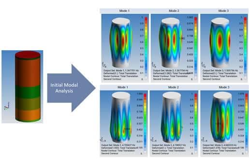
FEA Application for Industrial Equipment
Finite element analysis, or FEA, is a powerful tool for evaluating structural performance under realistic operating conditions.
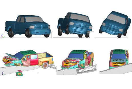
Roadway Transportation Safety with FEA
Transportation safety testing, particularly crash testing, is a complex and costly process. It involves replicating real-world scenarios that require highly advanced equipment and open-space test locations.
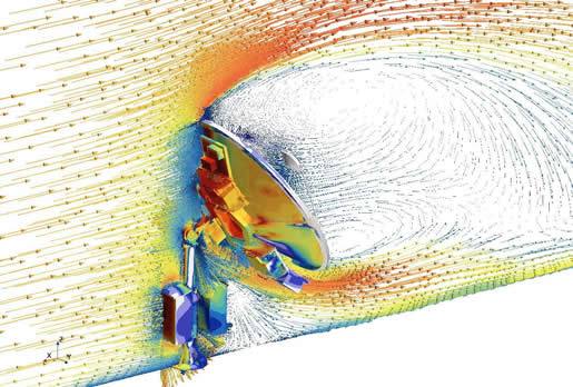
Wind and Water Loading on Antennas, Vessels, Buildings and Dams
A key challenge to any analysis project is load determination, although one can use formulas and code guidelines to approximate wind and water loading (e.g., ASCE/SEI 7-22 which supersedes ASCE 7-16), these approximations provide guidance but can leave stru
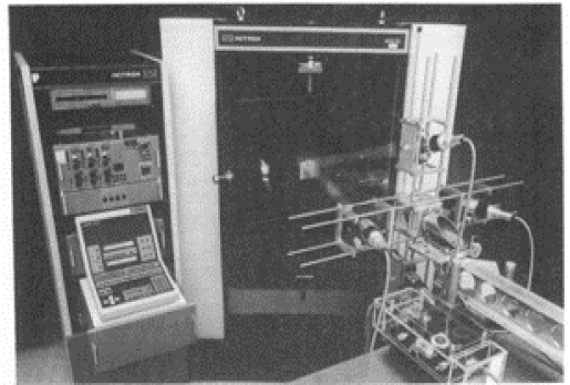
Fracture Mechanics and Finite Element Analysis: Catastrophic to Damage Tolerance (NASGRO)
Welcome to our overview of Predictive Engineering’s FEA consulting services in Fracture Mechanics and Damage Tolerance. We are realists in the world of virtual simulation. That is, we are

FEA Consulting Services 2020 - A Snapshot
We are FEA engineers that are generalists across pretty much all industries. The big difference we bring to our clients is our experience over the decades to ensure that our simulations reflect realty and are not cartoons.
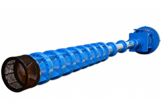
Vertical Turbine Pump – Vibration and Stress Analysis for Submerged Structures per ASCE 4-98
In general, this is an easy and straightforward FEA analysis. In the case of this project, a bit more preparation was required before running through the standard steps of the FEA procedure.
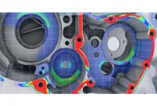
Norton Motorcycle Crankcase Analysis
Analysis Challenge:
However, the real challenge was calculating the various load sets.Along with the main crankshaft power stroke, inertia forces from the main crankshaft and balance-shaft must be considered, and of course, the traction torque of

NASA 5020A Requirements for Threaded Fastening Systems in Spaceflight Hardware
A big advance over the last couple of years has been our approach to fastener modeling. In prior work, fasteners were idealized using beams and rigid links, while nowadays, our preference is to use 6-DOF springs in combination with rigid links.
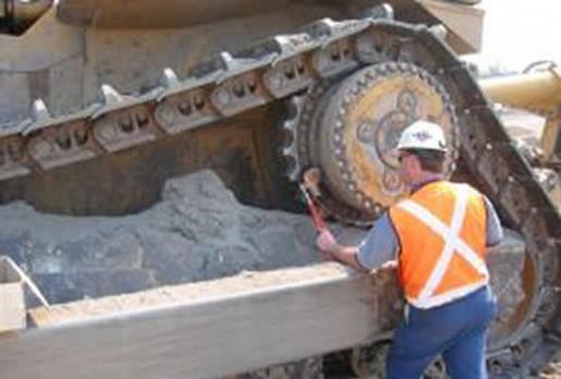
Sprocket and Hub Bolt Analysis on Slip-Critical Mining Equipment
This project analyzed a large segmented sprocket and hub system under various chain loading conditions and interpreted the bolt stresses using the NASA 1228 bolt design criterion along with the MIL-HDBK-5J standard.
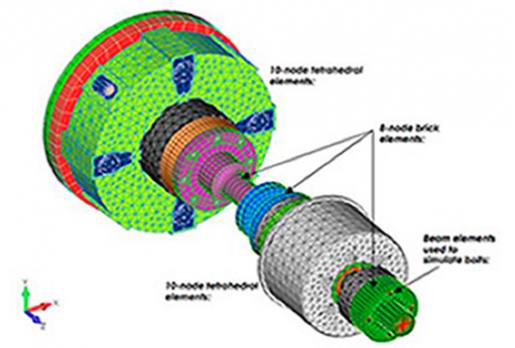
Cold-Spinning of Engines via the Perfect Drivetrain: Static and Eigenvalue Analysis
Ideally, the drive motor that is doing the spinning only transmits pure, clean torque energy to the test motor.
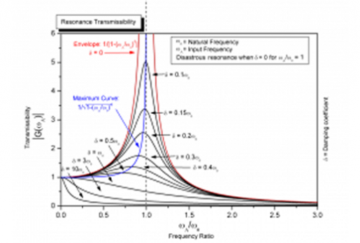
Vibration Analysis Consulting Services at Predictive Engineering
Besides linear dynamics, we have experience in nonlinear transient dynamics using LS-DYNA where the nonlinearity is low but the vibration response is deadly.
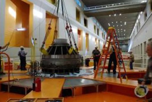
Hydroelectric Dam Thrust Collar Stress, Weld and Fatigue Analysis
No preparation of the gussets or weld penetration is assumed. That is, the load is transferred entirely through the fillet welds. Figure 2 shows how the FEA model was constructed by showing a cutaway of the gusset/bottom plate intersection. 
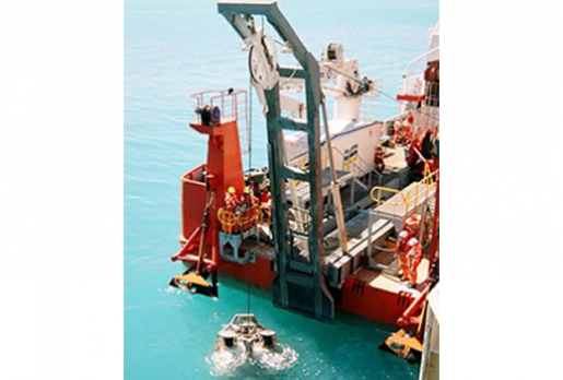
Ship Mounted Crane Analysis under DNV Rules
Two recent projects are discussed that cover the analyses of a ship-mounted crane for the launch and retrieval of a remotely piloted deep sea drill and that for top drive drill assembly used in the north sea oil patch.
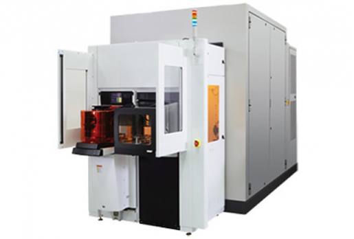
Seismic Analysis of Stationary Mechanical Equipment
Section 1: LINEAR ELASTIC ANALYSIS WITH Simcenter NASTRAN
A seismic study of the base frame for a 20,000 lb electron microscope (see Figure 1) was performed to ensure that the structure would meet ASCE 7 (American Society of Civil Engineers) and I
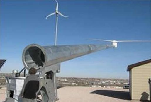
Dynamic and Static Stress Analysis of a Hinged Wind Turbine Tower
A shell geometry model was constructed and meshed with 4-node plate elements. Bolted connections were modeled with a combination of beam elements for the bolts and rigid links to connect the beam elements onto the plate mesh (see Figure 2).
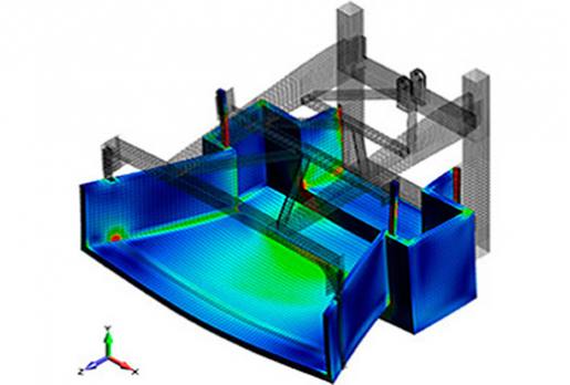
Analysis and Optimization of Fiber Reinforced Composite Structures
Composite Revolution

FEA Consulting Services: Transmissions, Gearboxes and Drive Train Components
This case study presents a few of our more interesting FEA consulting service projects that we have done on transmission, gearbox and drive train components over the last several years.
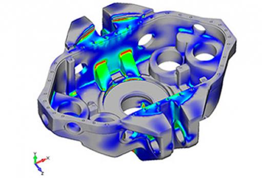
DNV (Det Norske Veritas) Certification Earned on Off-Shore Drilling Package
The drilling package engineering and manufactured by PREP consists of a draworks and the top drive unit. The photos really say it all.
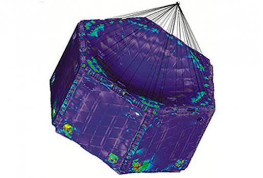
FEA PSD Analysis of Advanced Aerospace R&D Satellite
Revolutionary Satellite Solution Features Modular Design
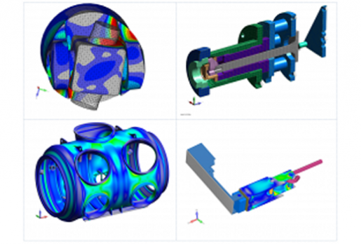
Insight Through Numerics: The World of FEA Consulting Services at Predictive Engineering
This short overview presents project work on:
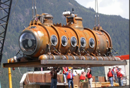
Stress and Buckling Analysis Deep-Diving Submersible Vessel per ABS Rules
Results from this analysis were used to certify the submarine hull under ABS rules.
For the buckling analysis, a specialized brick and plate model of the complete vessel was developed.
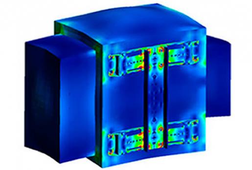
Static and Seismic Analysis of a Pole Mounted Electronics Enclosure
Modeling Assumptions and Details: The finite element analysis (FEA) model was constructed based on geometry provided by client.
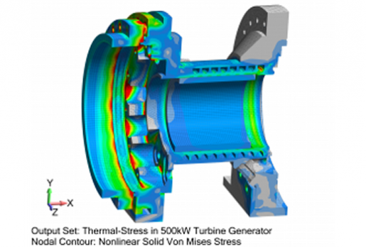
Thermal-Stress Analysis of Reactors, Turbine Generators, Composite Mandrels, Pressure Vessels and CFRP Structures
Below you'll find an onsite synopsis, a short summary video, and a PDF case study of the following thermal-stress projects that we have done using Femap, NX Nastran and LS-DYNA:
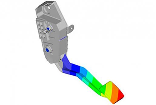
Nonlinear Finite Element Analysis FEA of Plastic Throttle Pedal
Modeling notes: material non-linearity was also included in the analysis strategy to better understand the elastic-plastic deformation response of the Nylon 66 throttle pedal.
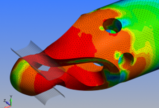
Advanced FEA Stress Analysis of Medical Instruments and Devices using Femap, NX Nastran and LS-DYNA
Complex analysis demands were only part of the challenge for these projects since the medical industry also requires extensive documentation and quality assurance that the models are built per specification. Additionally, in several cases the clients

Mobile and Aerospace Antenna Stress and Vibration Analysis
A vehicle mounted antenna was analyzed (see Figure 1) for stress, deflection and natural frequencies. This analysis inspected the resulting stresses based on pressures generated by a CFD drag analysis of the antenna moving at 80 MPH down the road.&nbs
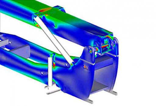
Lift Truck Analysis and Validation
Analyzed a completely new lift truck design leveraging existing commercially viable designs from other manufacturers. The mechanical analysis included the whole lift truck structure from boom to hydraulic cylinders to engine compartment frame to the axles.
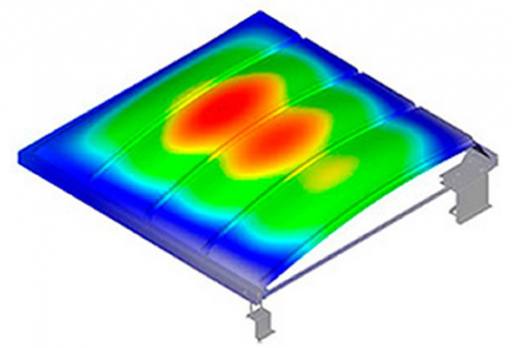
Structural Analysis Modeling and Optimization of a Plastic Solar Panel
Modeling notes: stress-stiffening was incorporated into the model to more accurately predict the polycarbonate glazing's deflection and stress behavior.
Stress and PSD Analysis of Lightweight Patient Stretcher for Airborne and Military Applications
Introduction: Predictive Engineering was engaged to assist a large air transportation and medical emergency services company develop their next generation of patient stretchers.
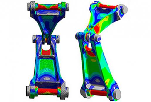
FEA Structural Analysis of Commercial Aircraft Landing Gear
This FEA analysis opportunity presented itself recently during work collaboratively performed with a global aircraft equipment manufacturer in the analysis of new gear sets for a large commercial airplane.
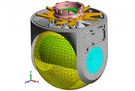
Vibration Analysis of Engineered Structures and Systems
Numerical vibration analysis is one of the core skill sets at Predictive Engineering.