Hydroelectric Dam Thrust Collar Stress, Weld and Fatigue Analysis
Analysis
Objective
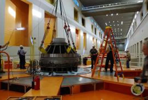
During the inspection of a thrust bearing at a hydroelectric dam, cracks were observed at the welds of the gussets of the thrust collar. This instigated the inspection of other thrust collars at the facility and similar cracks were noted in each of the thrust collars. It was clear that analysis was necessary to determine the root cause of the cracking in the collars.
No preparation of the gussets or weld penetration is assumed. That is, the load is transferred entirely through the fillet welds. Figure 2 shows how the FEA model was constructed by showing a cutaway of the gusset/bottom plate intersection. The free face of at the bottom of the gusset can be seen because the mesh of the two components is not merged.
The first step was to investigate a variety of load cases to determine the most likely culprits. Excessive interference fit between the shaft and the collar was analyzed using surface-to-surface contact. Dead weight and thrust loads were analyzed using rigid body element (RBEs) and body acceleration loads. Disassembly loads were applied using convective heat transfer. After all loads were analyzed and post-processed, the most likely causes of cracking were investigated further.
To simulate the heating load induced by the torches used during disassembly, a transient thermal analysis was done using convective heat transfer. Although temperatures and film coefficients for the torch could be approximated, the disassembly load cases proved to be scenarios of high interest and a more detailed approach was required. A physical test was performed on thrust collar with the same torch that was used during disassembly; temperatures were recovered using a thermal camera. The physical test was replicated with an FE model and convective heating was applied to the model with a range of both temperatures and film coefficients. The data from the FE model was plotted with the data from the physical testing to determine the combination of film coefficient and temperature that would best simulate the torch heating (see Figure 5).
Through this assortment of modeling and analysis techniques, the root cause of the cracking was determined. This allowed the hydroelectric dam engineers to establish a safe and effective disassembly technique for future thrust bearing designs.
Along with the stress and weld analysis, the model was analyzed for fatigue life based on a linear elastic fracture mechanics (LEFM) approach using the size of the largest crack to calculate the stress intensity factor (K1). The stress intensity was calculated to be far below the mateirals critical stress intensity factor and below a reasonable fatigue crack initiation. Fatigue life prediction indicated that the cracks would be stable and that catastrophic failure would not occur during normal use.
PDF Download


")
