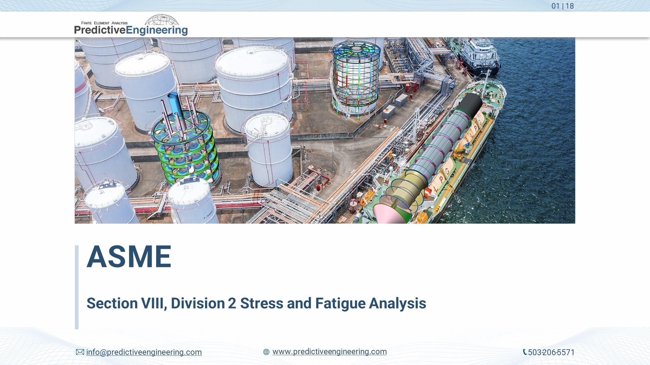
ASME BPVC: Pressure Vessel Consulting Services
Introduction
Over the last 20+ years, Predictive Engineering has tackled some of the most complex applications of the ASME BPVC Section VIII, Division 1 Rules for the Construction of Pressure Vessels (BPVC.VIII.1), Division 2 Alternative Rules specifications (BPVC.VIII.2) and Division 3 Alternative Rules for the Construction of High Pressure Vessels (BPVC.VIII.3)
- Stress and fatigue analysis of large-diameter nuclear waste recycling vessels under NQA-1 requirements
- Vessels with internal piping and structures subjected to sloshing, seismic and added-mass effects
- Transient thermal-fatigue of thick-walled tanks
- Lifting and transportation analyses
- Buckling analysis via ASME formulas, Eulerian and Nonlinear methods
- Differential thermal-stress analysis of heat exchanges with mixed materials
- Elastic-plastic stress for Protection Against Plastic Collapse
Within this body of work, we have applied the following codes:
- ASME BPVC Section VIII, Division 1 Rules
- ASME BPVC Section VIII, Division 2 stress, plasticity, and fatigue
- ASME BPVC Section VIII, Division 2 stress, plasticity, crack-growth and fatigue
- ASCE 4-98 with added-mass applications for normal modes analysis.
- ASCE 7-16, AISI N690 and ABS
To support our pressure vessel work, we have written custom software for stress and fatigue evaluation of thin and thick-walled pressure vessels.
Our careful and meticulous pressure vessel consulting service work has allowed us to classify tanks and vessels as “fit-for-service” that would typically have required extensive rework by hand-calculations. Clients come to us when they need high-quality work executed and documented to withstand the most rigorous reviews whether DOE, Bechtel, GE Water and Gas or SpaceX.
These FEA pressure vessel consulting projects cover a wide variety of analyses, from differential thermal-stress analysis of heat exchangers utilizing mixed materials, to stress and fatigue analysis of large-diameter vessels, to analyses of vessels with complex internal structures subjected to sloshing, seismic and added-mass effects or lifting and transportation analyses and transient thermal-fatigue of thick-walled tanks. We have also done stringent code work under the ASME PVHO and ABS Underwater Vehicles, Systems and Hyperbaric Facilities on several types of passenger submarines. In one particular case, our FEA PVHO-ABS consulting allowed our client to certify their submarine via FEA in lieu of the standand design rules. This exception was approved by the ABS since the FEA results tightly correlated with the strain-gauge results from the dive test. More results on this investigation can be found at NASA Tech Briefs
To support our pressure vessel work, we have developed custom software for stress and fatigue evaluation of thin and thick-walled vessels. Some of this PV consulting work has helped SpaceX launch their next generation of rockets.
In the nuclear field, Predictive is certified to generate NQA-1 seismic, buckling and fatigue analysis reports on some of the most complex vessels installed at the Hanford Tank Waste Treatment and Immobilization Plant. These reports are all focused on the "design-by-analysis" rules within the ASME Section VIII, Division 2 specification. Working collaboratively with Department of Energy contractors, Predictive has pioneered many of the seismic and buckling analysis procedures based on interpretation of ASCE 4-98 and ASME Section VIII, Div. 2 Codes for pressure vessels containing large submerged internal components that are subjected to the added mass requirements within ASCE 4-98.
From seismic to buckling to fatigue analysis, Predictive can assist in validating the most challenging pressure vessel designs. Our hard-earned experience allows us to safely classify tanks and vessels as “fit-for-service” that would typically have required extensive rework by the standard ASME Section VIII, Division 1 hand-calculations.
In brief, clients come to us when they need high-quality work executed and documented to withstand the most rigorous reviews.
Please download our project portfolio for our ASME BPVC pressure vessel consulting services
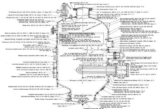
ASME Section VIII, Division 1 – Rules for the Construction of Pressure Vessels
Reactor Design Review
Reviewed two high-temperature ASME vessel designs for ASME Section VIII, Division 1 Code compliance. One of our favorite perks in this industry is being involved with design and analysis of emerging technologies, this was one such project. The client also provided their own custom calculations for a proprietary clamp design which required detailed analysis. Ultimately these one-of-a-kind designs received some minor updates and were fully stamped for production.
Full Service ASME 8, Div 1 Design Expertise
Predictive Engineering works with multiple clients, providing complete vessel and heat exchanger design per ASME Section VIII Division i. Design services can include internal/external pressure calculations, wind & seismic loading, piping loads, saddle/lug/basering support analysis, lifting & transportation loads, and much more. We often provide calculation support and can provide CAD drawing services in 2D and/or 3D. Recent examples include a 138” OD x 312” tall stainless-steel tank for the brewing industry, a 72” OD x 1566” tall stainless steel tower used in chemical processing, and a 96” OD x 966” tall distillation column.
Evaluation of a non-ASME tank for Code Equivalency
Our client was denied an operating permit for a large electron microscope installation due to the fact that their voltage generator tank was not ASME stamped. It had been designed and built in Japan to the JIS B 8265 pressure vessel standard and then shipped to the USA for operation. Predictive’s solution was to compare the JIS material test reports used to ASME approved materials, select the closest matching ASME material specifications, and precisely model the existing tank dimensions and features so that an equivalent ASME Section VIII Division 1 calculation could be completed. Fortunately, the analysis showed that the vessel was safe to operate at its intended design conditions, and the client was able to operate their microscope.
ASME Section 8 Batch Furnace Optimization
For this project, a dated vessel design was re-vamped to improve performance and reduce maintenance costs. The main problem revolved around a heating element nozzle that tended to lose cooling efficiency from a jacket. The design was re-built in the latest ASME Code design software which revealed some concerns with the original jacket geometry. A revised jacket and an updated internal insulating sleeve were detailed out for the client. We combined this with an FEA and CFD of the new geometry to in a more efficient functioning furnace
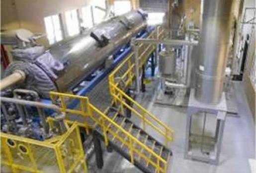
Pressure Vessel Auger Optimization
Not every pressure vessel is a simple cylinder, sometimes you have to get creative with shapes to solve a problem. We have plenty of experience with odd shapes and aren’t afraid to think outside the box. We ran a design optimization project for an Auger which is a rotating pressure vessel and a heat exchanger all in one. Unfortunately, the original design was experiencing some early failures. Predictive employed both our Division 1 Pressure Vessel and our Division 2 FEA services to produce an optimized Auger design that will withstand it’s unique loading conditions for years to come. Our client followed-up a year later to have us analyze and update a similar, but different sized auger in the same manner.
Vessel Design Review
Multiple clients utilize our services for ASME Code design review. This process is completely customizable based on the needs of the client or the project. No matter the size, scope, or complexity, our goal is always the same: review every portion and aspect of the design for code compliance and for the possibility of optimization. Recent vessels include a 138” diameter x 312” tall jacketed Brite Tank; 7 separate columns of differing sizes complete with internal trays, insulation, ladders & platforms, nozzle loading, transportation and lifting analysis, and more… the tallest of which was over 130 feet; and a 41” diameter heat exchanger with custom flanges and an expansion joint.
Zirconium Columns
Designed three columns in solid Zirconium 702, two 11.5’ dia x 92’ tall and the other 9.5’ dia x 135’ tall. The combined value of this equipment was over $15M. The design work encompassed full ASME Section VIII Division 1 calculations and complete fabrication detail drawings including internals, externals, skirt, nozzle loading, wind/seismic, lifting, and transportation.
Various Vessel Project
Designed 17 pressure vessels in alloys C276, Alloy 825, Alloy 20, and AL6XN in sizes ranging from 3’ dia up to 14’ dia. Many of these vessels were categorized for “lethal service”. Some were Jacketed for heating or cooling, and some included Agitators for mixing. This project was especially challenging due to the large quantity of different designs with a shared completion date.
Flue-Gas Energy Recycler
Designed a Kettle type steam generator with U-tube exchanger for increasing plant efficiency. The high-heat spent gases are used in this exchanger to continuously generate steam for use in other sections of the plant. A rare alloy was used to withstand the 1400F inlet temperature and FEA was employed to analyze thermal gradients and identify high stress areas of the design. Portions of this exchanger operate in the creep range, requiring unconventional design and fabrication considerations.
Titanium Vessel with Half-Pipe Jacket
Designed an 8’ dia. titanium vessel with spherical heads and an integral half-pipe jacket. All design elements were optimized to limit material thickness, reducing cost. Vessel details included internals, lifting trunnions, and support legs in titanium.
Tantalum Heat Exchangers
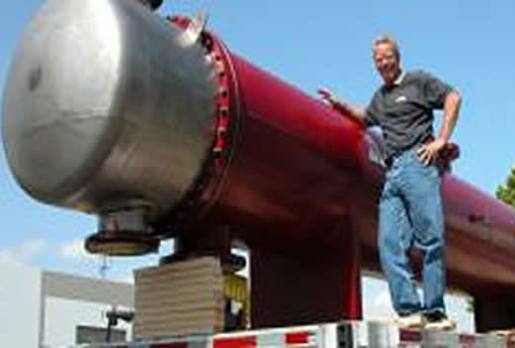
Designed multiple shell-and-tube heat exchangers for hydrogen service and for steel pickling. Tantalum is extremely expensive and thus, is used as a loose or clad liner applied to steel parts. This requires specific design considerations and specialized calculation methods. One such design was a 24” dia. x 353” long with tantalum-clad bonnets worth $1.4M.
Nitrous Cooler Condenser
Designed a 90” ID x 405” long condenser for processing Nitrous Gas. The equipment included a vapor-belt style shell impingement segment at the inlet and outlet which also acted as expansion joints. Over 2400 titanium tubes were used within the design, each roller expanded and seal welded at each end. The entire exchanger was design to sit at an angle to allow for full drainability.
Zirconium Reboiler
Designed a 36” ID x 144” long heat exchanger which mounts to the bottom end of a chemical processing column. This steam heater included a vapor belt and a flanged and flued expansion joint. The tubesheets were explosion clad to join Zirconium to 3” thick carbon steel. The bonnets were solid Zirconium with removable cover flanges for cleanout.
Titanium Storage Tank
Designed a 12’ dia x 12.5’ tall storage tank for caustic medium. This tank was made completely from Titanium Grade 7 and stainless steel backing flanges. It also included 26 separate nozzles and multiple dip pipes and internals. This tank was designed both to ASME Section VIII and API 620 to ensure longevity and safety.
Tantalum Bayonet Heater
Designed tantalum bayonets which are inserted into storage and processing tanks to heat their extremely corrosive contents. These bayonets introduce heat similar to a U-tube exchanger except that the steam is injected at the end of capped tantalum tubes. The steam and condensate then falls back into a collection chamber to be reused. This one-way flow method of steam heating provides a more consistent heat delivery and a convenient separation of condensate.
ASME Section VIII, Division 2 – Alternative Rules
Optimization Stress Analysis of Rectangular Gate Valves
A series of high-pressure (1,400 psi) rectangular gate valves were optimized to meet the ASME Section VIII, Division 2 “Design-by-Analysis” stress classification requirements. This type of BPVC FEA consulting service is a key skill set for Predictive Engineering, having more than +20 years serving the pressure vessel manufacturing industry. We analyzed three different gate valve designs, and working collaboratively with our client, optimized the designs to meet the BPVC.VIII.2 stress criteria for surface, membrane and peak.
Thermal Deflection Analysis of Heat Exchanger
An Inconel heat exchanger had tight deflection requirements for its nozzles and our client wanted an accurate idea of how the heat exchanger would deflect under operation. The ASME Section VIII, Division 2 (BPVC.VIII.2) FEA model used the inlet helium flow at 1,400 F to and the oil-filled tubes at 500 F to map a steady-state temperature field. This temperature field was then used as the loading for the thermal-deflection model. Predictive’s ASME BPVC FEA services were able to provide our client a quick turnaround and design insurance that the vessel would meet their deflection requirements.
ASME-VIII-2 Stress Analysis of Blind Flange
This project provided ASME Section VIII, Division 2 FEA Engineering for a blind flange design. An FEA model was developed in compliance with ASME Section 8 requirements, using provided design parameters, including a pressure of 800 psi at 200°F. The analysis evaluated stress classification based on ASME BPVC Section VIII, Division 2 standards. A hydrostatic test case with 1200 psi internal pressure was also conducted to verify performance. The analysis confirmed that the flange met all criteria for ASME Section 8 Div 2 certification, ensuring its structural integrity under both design and test conditions. This work aligns with best practices for pressure vessel analysis and supports compliance with ASME pressure vessels certification standards.
ASME Section VIII, Division 2 Design Verification of a Bottom Head Nozzle
Due to forging and manufacturing limitations, the bottom head nozzle required Division 2 “Design-by-Analysis”. Predictive’s BPVC consulting services were contracted for the project and the analysis was completed in a matter of days. Finite element analysis of the head showed that the current design would meet the ASME allowables and that the recessed threaded bolt holes would not be a problem.
Stress Analysis of Dual (Condenser-Evaporator) Heat Exchanger System
This ASME Section VIII, Div 2 analysis was for one of the world’s largest HVAC companies. Their new condenser-evaporator system presented several manufacturing challenges due to its size and the tubesheet thickness requirements via ASME Section VIII, Division 1 calculations. Predictive was hired to perform an Division 2 analysis and to investigate how to optimize the tubesheet design. Geometry was idealized into surfaces and then meshed with shell elements. The tubesheet was meshed with brick elements with the tubes as beam elements. Thermal-stress analysis of the tubesheet showed that its design was optimal given the design constraints. Stress results on the complete system showed that it met the ASME Section VIII, Division 2 requirements. A stamped PE report by a consulting engineer skilled in ASME analysis was delivered to the client.
Fatigue Analysis of LP-Nitrogen Rejection-Unit (NRU) Column under Wind Loading (CFD)
The oil and gas processing industry is well-known for their safety standards given their challenging history. During placement of their 50 ft tall LP-NRU column within a large oil refinery, significant swaying of the column was noticed under moderate wind loading. The immediate concern was whether this cyclic movement would invalidate the column’s ASME Section VIII, Division 1 specifications. Predictive Engineering was hired to determine the wind loading pressures on the column and then perform a ASME Section VIII, Division 2, Part 5.5 Protection Against Failure from Cyclic Loading analysis. This type of work is standard at Predictive with over 25 years of ASME BPVC FEA consulting experience. A CFD analysis was conducted on the column using wind speeds at 20, 60 and 100 mph. Wind pressures were mapped onto the structural FEA model and analyzed. Stress results were interrogated based on ASME sec 8 Div 2 guidelines and compared against the material’s ASME allowables. Results showed that the column meet the ASME allowables under the most extreme wind loading. Fatigue analysis showed that the column would meet its 20-year service life under the historical wind speed patterns of that region. Our stamped PE report provided the necessary documentation to allow our client to proceed with the installation and operation of the column.
ASME Section VIII, Division 3 High-Pressure Fatigue Analysis
Extraction vessels, whether for hops or marijuana, operate well within the ASME Section VIII, Division 3 Alternative Rules for Construction of High-Pressure Vessel realm. These high-pressure vessels require special care and feeding, and if they fail in service, lawsuits are inevitable. In fact, Predictive Engineering was involved in such a case of a hop extraction vessel that failed in service resulting in a death of a worker. The manufacturer designed the vessel using Division 1 guidelines and had since gone out-of-business. Long story, but our analysis work showed that failure initiated at the inside corner of the lock-ring groove and catastrophically propagated. Forensic analysis confirmed our analysis results. Given this background, it was an easy choice for our client to select Predictive Engineering’s FEA Pressure Vessel Consultants for this project. Due to the cyclic service requirements for our client’s high-pressure extraction vessel, the analysis work required numerous design optimizations to lower the lock-ring notch stress. Under ASME Section VIII, Division 3 fatigue rules, an Article KD-3 Fatigue Evaluation and a KD-4 Fracture Mechanics Evaluation were performed using the NASGRO suite of programs for fracture and fatigue. Results from the KD-401(c) – Failure Assessment Diagram (FAD) showed that the modified vessel (stress-relief groove within the lock-ring notch) would pass our client’s fatigue requirements. The fracture initiation work assumed a smallest detectable crack size according to NASA-STD-5009B – Minimum Detectable Cracks Sizes for Fracture Analysis. This was a very successful project since we were able to take our client’s initial un-economical and un-manufacturable design and convert it into a very profitable and very manufacturable high-pressure vessel that met all Division 2 and Division 3 code requirements.
Composite Overlay Pressure Vessel (COPV) Stress and Burst Analysis
Aviation, aerospace, automotive, etc. are all moving toward composite pressure vessels. Although expensive, the advantages of composite overlay pressure vessels (COPV) can’t be denied. Our client required an aerospace grade analysis of the COPV, Type III vessel analysis from thru preliminary design review (PDR) to final critical design review (CDR). The analysis sequence goes from autofrettage of the aluminum liner to improve its fatigue life, operational pressure loading and then to burst. Thus, our client required consulting engineers with expertise in ASME vessels, nonlinear FEA and a keen understanding of composites and their failure mechanisms. The autofrettage process was simulated by pressurization of the digital prototype past the aluminum liner’s yield stress and then removing the pressure. The resulting plastic damage in the liner then places the liner under a compressive stress state. As the vessel is then pressurized in service, the liner’s fatigue life is significantly increased. This work also required the use of NASGRO damage and crack growth calculations to demonstrate that the liner would remain intact during its surface life. Final burst analysis of the COPV was benchmarked against the client’s experimental data and showed almost one-to-one correlation. For CDR, our FEA consultants’ engineering report was reviewed by the external engineering team and was accepted with only minor editorial comments. It should be mentioned that the highlight of this project was the validation of the COPV model against our client’s experimental results.
ASME Section VIII, Division 2 Stress Analysis of Pipe Stubs
Prior work by our client using an ASME Section VIII, Division 1 rules-based software program indicated that their large-diameter pipe stubs did not meet Division 1 requirements. To obtain a satisfactory design, they were recommended to contract with Predictive Engineering for Division 2 numerical calculations. Our ASME FEA consultants were able to show that their initial design was un-workable and that the pipe stubs had to be attached at right-angles to the main pipe to meet code requirements. After numerous design iterations, our client was able to propose a redesign to the system that would then easily meet the Section VIII, Division 2 code specifications. Predictive also provided Section VIII, Division 1 calculations to the client to demonstrate that other similar designs were inadequate. Our goal is to be advocates for the most efficient pressure vessel design whether under Div. 1 or 2 code requirements.
Molecular Sieve Pressure Vessel
An ASME Section VIII, Division 2, Part 5.5 Protection Against Failure from Cyclic Loading analysis was performed for our client. Another description for this analysis title for this work might be “Just another ASME fatigue analysis of a pressure vessel”. Although it was just another for our FEA pressure vessel ASME consultants, we take every project seriously. As someone familiar with the code, we were pleased to see that the most recent ASME update is requiring that Division 2 work “Design-by-Analysis” be performed by a “Certifying Engineer” which must be a PE with at least 4 years recent and relevant ASME design experience. Given that Predictive has more than 20 years of relevant ASME design experience, we were the logical choice for our client. The ASME Part 5.5 fatigue analysis showed that the pressure vessel met the design requirements of more than a million cycles and the project was wrapped up. As we like to tell our clients, in the 30-year history of Predictive Engineering, we have never had a lawsuit or an analysis failure. We take every project personally to ensure that it will be successful.
Flash Tank Nozzle Analysis
Our client initially had designed the system under ASME Section VIII, Division 1 rules but found that the Division 1 rules specified nozzle reinforcement pads that were uneconomical and furthermore, almost impossible to manufacture. Based on Predictive Engineering’s experience with the FEA services toward the “Design-by-Analysis” or Alternative Rules, a consulting contract was initiated to create a new nozzle design that would meet the ASME Section VIII, Division 2 requirements. FEA results allowed the client to significantly reduce the nozzle repad and sizing and still meet code specifications.
Marine Growth Prevention System – Pressure Vessel Vibration and Shock Analysis
Since the piping systems within ships and submarines are supplied with sea water, there is a threat of marine organisms growing and depositing on the inner surfaces of the pipes. These vessels use copper anodes to generate ions in the seawater system that minimize organism grown and marine fouling. However, these marine grown protection systems (MGPS) must be designed robust enough to withstand the harsh vibration environment of the ships’ engine rooms. Given that this particular MGPS was to mounted to a naval submarine, loads included random vibration, shock and pressure loading. This analysis determined, through Finite Element Analysis (FEA), stresses, deflections, eigenvalues, and fatigue life of the MGPS vessel in accordance with the guidelines set forth in ASME Section VIII, Div 2. The analysis was performed to provide confidence that the equipment can withstand the transmitted shock acceleration and remain captive.
Water Purification Vessel Weight Optimization using ASME VIII Div. 2 – Design by Analysis
Semiconductor manufacturing requires massive amounts of ultrapure water (UPW) and generating that water requires advanced pressure vessel systems. While ASME VIII Division 1 (Design by Rule) provides clear guidance for designing safe pressure vessels without complicated analysis, it can lead to rather overbuilt structures. This design under the scrutiny of this analysis contains several penetrations in the top vessel lid and was therefore reinforced by increasing the thickness of the vessel lid per Div. 1 rules. However, it was suspected that the thickness mandated by Div. 1 was far more that required for a safe vessel. Using the design pressure and bolt preload as the driving loads, the thickness of the heads and flanges in the FEA model was reduced until peak stresses approached ASME allowables. The final product of the optimization study had reduced head thickness by 55% and flange thickness by 30%, significantly reducing material costs and the overall weight of the system.
ASME Section VIII, Division 2, Part 5.5 – Protection Against Failure from Cyclic Loading
Although not a classic pressure vessel application, our client was required to meet the ASME Section VIII, Division 2, Part 5.5 requirements for fatigue due to its high-cycle service environment. The structure was a new design for the client where prior experience had indicated multiple fatigue failures. Our work was to assist their design team toward improved manufacturing processes around critical fatigue weld locations and also to stiffen the design to meet design requirements. The structure is now in service and operating.
Fatigue Analysis of Molecular Sieve Vessel under Alternating Pressure Loads
Weld fatigue analysis is particularly well defined in the ASME Section VIII, Division 2 code and for pressure vessel manufacturers, it provides for a high-degree of confidence that a vessel will meet the life-cycle service requirements. From a FEA simulation engineer viewpoint, what we like is how the ASME code classifies weld quality in terms of fatigue strength reduction factors. Given accurate stress numbers, the ASME code provides a direct methodology to calculate the fatigue life at welds and of course, in the rest of the vessel. In this particular analysis, our fatigue load was an alternating pressure from 5 to -1 bar (75 to -15 psi) and fatigue service life was then given for the various nozzle welds, head flange and other components.
High-Pressure Circulating Pump Housing
Thick-wall pump housings under high-pressure (17.6 MPa) are not easily analyzed with standard ASME off-the-shelf programs and the interpretation of the ASME Section VIII, Division 2, Part 5 – Alternative Rules does require some tricks. Our international client was in the process of designing a new class of pump housings with diameters greater than 2 meters and wall thicknesses of over 100 mm. The weight of one such housing was over 60 metric tons. Our goal as ASME consultants was to demonstrate that the initial design would pass the ASME classification and also to show where material could be trimmed from the massive forging. One would call this “Digital Prototyping”. Results showed that several tons of material could be removed from the housing and still meet the ASME classification. This trimmed material saved our client tens of thousands of dollars and more than paid for the FEA service work.
High-Cycle ASME Fatigue Analysis of Hydroelectric Turbine Discharge Ring Nozzle
Predictive Engineering was tasked with performing a follow-on stress and fatigue analysis of a large-diameter hydroelectric turbine discharge ring nozzle in support of our client’s legal case. Our role as expert witnesses, was to provide an independent assessment of the high-cycle fatigue life of a large, welded structure using the ASME Section VIII, Division 2, Part 5.5 Protection Against Failure from Cyclic Loading. The discharge ring nozzle was fabricated as two 180-degree sections and then bolted together to form the nozzle. The nonlinear FEA model simulated the bolted flange connection and it slip-ring connection to the downstream flange. The nozzle loading was thru mapped CFD generated turbine blade pressure loads. The model was then validated against operational strain gauge measurements. As part of this project, the opposing council’s engineering report was reviewed and critiqued. Our results independently demonstrated that, once the welded regions were ground smooth and inspected per ASME Part 5.5 weld quality requirements, the nozzle rings would meet their 20-year service requirement.
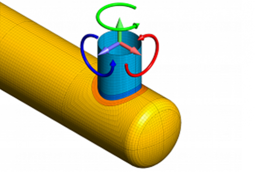
ASME Fatigue Analysis of Twin-Screw Auger
It is not unusual for our clients to come to us with undefined failure problems, and thus requires us, to be forensic engineers to determine why the structure failed. The structure in distress was a 40 ft long twin-screw auger used to thermally process semi-solid liquid bio-waste into a clay-like material. As the bio-waste enters the auger, the flights of the auger are heated and then dry the bio-waste as it is moved down the length of the auger. After several years in service, the shell of the auger supporting the flights cracked at a welded location. Standard static stress analysis indicated that failure should never have occurred. Although the auger is not a pressure vessel, the ASME code provides detailed guidance on how to treat stresses at welded connections. If the weld is uninspected and is not full-penetration, then a stress multiplier of 4x is required. Given this multiplier, it was obvious that normal operational loads were sufficient to induce fatigue failure. Going forward, the auger was redesigned to avoid welded connections in high-stress locations and the project was closed out. The interesting twist to this project is that our strength at Predictive Engineering is that we are generalists in simulation and have broad knowledge of a variety of engineering codes to guide us in our forensic engineering and more importantly, how to quickly determine the most efficient design solution to ensure a robust structure.
Regenerative Thermal Oxidizing Vessel
This type of work might be described as our bread and butter of the ASME Section VIII, Division 2 FEA stress classification work. This last analysis is just one of many that we have done for this company. Even given this history we were able to make several design changes that improved its robustness with very little additional cost.
ASME Suitability Assessment of Evaporator Vessel for Complete Flooding
Our client had several evaporative vessels in service, that over the years had accumulated sufficient shell side residue that was hindering their efficiency. Given that the tube bundle section of the vessel was 30 m long and 4 m in diameter, the only economical manner to clean out the residue was determined to flood the vessels. The challenge was these vessels were never designed to be flooded and, without some sort of documentation or design modification, the only alternative would be to scrap the vessels and install new multi-million dollar evaporators. Through several rounds of finite element analysis (FEA) it was determined that the vessel would fail upon being flooded. At this stage, in collaboration with our client, it was determined that the lower tube sheet could be supported and with some minor reinforcements (e.g., nozzle repads), the vessel could be flooded and still fully comply with ASME Division 2, Section VIII specifications. The tubesheet support involved cross-bracing the bottom of the tubesheet using nonlinear contact between the support and tubesheet. It should be mentioned that the vessel was found to comply only via the plastic collapse section of the ASME code. To verify that the design would be robust, the hydrostatic pressure load was ramped up to 3x its flooded state, exceeding ASME’s requirement of 2.4x. For conservativeness, the material law assumed perfectly elastic-plastic behavior. At the end of this analysis, our client was confident that the vessel could be flooded and work is underway to build the support structure and then proceed with the cleaning operation thereby saving their company millions of dollars.
Static Stress Analysis of a Condenser and Tube Sheet
ASME Section VIII, Division 2 “design-by-analysis” was performed on a large condenser bundle that was to be integrated into a nuclear reactor heat exchanger. Due to a past failure the client had redesigned the condenser bundle and wanted to determine the axial forces and von Mises stress in the condenser inlet end water box and tube sheet interface. Two separate load cases were examined one at normal operating conditions and one at extreme operating conditions. One of the largest hurdles in this project was the massive size of the model; it consisted of almost 3 million 6-DOF nodes. The size of the model was driven by the tube sheet which consisted of 17,453 tubes tied into the sheet. To help limit the size as much as possible the tubes were modeled using beam elements. In order to accurately model the tube and tube sheet interface plate elements were used to model the first inch of tubes and the beams were attached to them using rigid elements. The analysis itself was a simple linear static model with a hydrostatic pressure load applied to the water box.
9X9 m Regenerative Thermal Oxidizer (RTO) Vessel
Our client was in the process of fabricating a new RTO vessel that represents a first in class of a 9X9 m unit. In order to verify the new design prior to fabrication, a finite element analysis (FEA) model was built of the structure to virtually simulated the mechanical loads seen during operation. The design guidelines used for the analysis consisted of ASME Section VIII, Division 2 “Design-by-Analysis” specifications with some margin based on the experience of our client. This type of analysis is part of Predictive’s core FEA pressure vessel consulting services. The upper portion of the vessel was modeled taking advantage of symmetry; however, the lower portion required a complete model with the weight of the upper structure distributed over it using Nastran RBE3s. The final analysis met our client’s design goals and the structure went into fabrication.
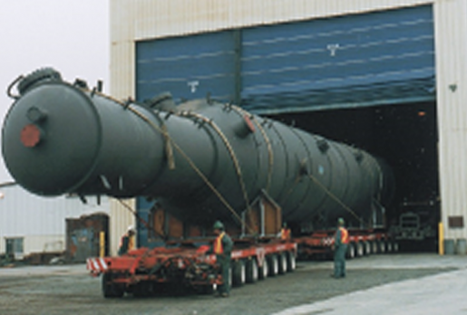
Rail and Truck Transportation Analysis of Large Concentrator Vessel
Our client was in the process of moving a large pressure vessel by rail and truck. It was necessary to evaluate and ensure that stresses during transportation met ASME Section VIII, Division 2 requirements to ensure no damage would be induced that would negatively affect the vessel during operation. Transportation load cases were provided by the client consisting of body acceleration loads. The analysis required working with our client (vessel fabricator) and the transportation company to design a restraint system that would comply with our analysis but also be economical and manufacturable. The final vessel configuration was approved and the vessels were moved successfully.
Thermal-Stress Fatigue Analysis of High-Temperature Graphitization Furnace
It seems rare nowadays that an ASME-type analysis is performed without an attendant fatigue analysis. We believe it is simply the result of a changing marketplace where our clients are becoming more knowledgeable in their requests and the industry as a whole are requiring greater accuracy in their analysis work. This project was chartered to investigate the service life of a high-temperature carbon fiber graphitization furnace. The company had several of these furnaces and they were more than 20 years old. Although they were designed to operate at 1650°C, our client wanted to increase the operating temperature to 1850°C to maximize production output. The work consisted of idealizing the thermal performance from graphite felt to water cooled steel shell. With this thermal loading, the FEA model of the system was analyzed under thermal and vacuum loading to create a matrix of possible operating states. The analysis work showed that the furnace was well designed and could safely operate at higher temperatures for many more years.
ASME 8, Div 2 Nonlinear Fatigue Analysis of Hairpin Heat Exchanger
This work was particularly interesting since the client had experienced fatigue failures along the weld line between the tubesheet and the shell. The complication on this analysis was that the use of compression sleeve fittings to join the components together. As the bolts were preloaded, tubesheet welded section would lock against the main heat exchanger shell. Our analysis work showed that the weld failure was due to over tightening of these locking bolts and not general thermal or pressure loading. The work required a complete nonlinear contact analysis with bolt preload and then application of design loads. The solution was simply to back-off on the bolt preload. This was quite surprising to all and saved significant costs to our client.
Fatigue Analysis of Multi-Chamber Stacked Chamber
A static pressure and fatigue analysis was performed for a four-cell stacked simulated moving bed (SSMB) column to evaluate whether it would meet ASME Section VIII, Div. 2 requirements. The structure was modeled in half symmetry with the most conservative side of the structure in the finite element model using a combination of plate and hexahedral solid elements. Fillet welds in the structure were modeled using rigid elements constraining only the translational degrees of freedom (DOFs). Releasing the rotational DOFs represent the physics of a single sided fillet weld and allow weld forces to be extracted quickly and easily. The analysis is linear elastic which allowed the stresses to be scaled linearly with pressure. A 75 psi pressure load was applied to the inside of the structure to evaluate the weld stress at the maximum possible pressure. The stress was normalized to a 1 psi load and then scaled to find the weld stress at each pressure in the operating cycle. Fatigue Essentials was leveraged to count the fatigue cycles using the rainflow-counting method and calculate the cumulative damage over the lifetime of the pressure vessel. The operating cycle of the SSMB pressure vessel was a series of repeating patterns which were stored as Fatigue Essentials Spectrums. The S-N curve for the material was added to Fatigue Essentials from ASME Section VIII, Division 2. With all of the data input into a Fatigue Essentials project file, the cumulative fatigue damage in the welds was calculated at the click of a button. The combination of linear analysis in NX Nastran and Fatigue Essentials provided an efficient, robust method to evaluate the fatigue life of a production pressure vessel. Not only were we able to confidently report to our client that their pressure vessel would not fail during the production
Stress Analysis of High-Pressure Ductile Cast Iron (SA-395) Hydraulic Manifolds
The challenge to use cast product for a pressure containing component under the ASME code is two-fold: (i) a 5x knock down factor from the material’s ultimate strength and (ii) inspection requirements to assure high-quality. To make it even more difficult, our client had pressures exceeding 1,000 psi within their manifolds and thus the ASME code requires a 90% quality factor for the casting. Three manifolds were analyzed using the FEA method with the stress results classed using a stress allowable of (60/5)*0.90 = 10.8ksi. On a numerical basis, the stress results showed that the manifolds would pass the ASME Section VIII, Division 2 classification but additionally, one had to substantiate how the casting could meet the 90% quality threshold. Based on Predictive Engineering’s metallurgical experience (AFS member and co-author of “Handbook of Abrasion Resistant Cast Irons”), it was determined that the DuraBar casting process would assure that the quality level would be met. Lastly, the client was informed that the ASME code also requires that all castings be hydrostatically tested to 2x their design pressure. This project presents a good example of how we strive to be advocates for a safe design while collaborating with our clients that it can still be manufactured and inspected in an economical manner.
Thermal-Stress Fatigue Analysis of Evaporative Hairpin Heat Exchanger
Our client requested this analysis due to prior fatigue failures at the intersection between the tubesheet and tubesheet channel (i.e., shell). Although this region was machined out of a solid steel billet, fatigue failures were still noted. Additionally, the hairpin heat exchanger used two large bolted flanges at each end for attachment of the shell side and tube side components. To correctly model these structures, the geometry was idealized into a solid brick finite element mesh with bolt preload applied using a beam element with shell elements at both ends to simulated the nut and head ends. Given the analysis complexity of bolt preload and contact, the model was analyzed using LS-DYNA as a nonlinear implicit analyses. The first step was to conduct a steady-state conduction analysis to create a thermal profile within the evaporator. Thermal-stress results were interpreted using the 2015 ASME Section VIII, Division 2 requirements and the evaporator was shown to meet the client’s required fatigue life. A side benefit of this work was the ability to show the client that several heavy components of their vessel could be reduced in section size and still meet code requirements.
Large Diameter (300”) Pressure Vessel Lifting Lug Analysis
The purpose of this analysis was to verify that jacking lugs used on several large diameter pressure vessels would not cause damage to PV components (such as the skirt, shell and cooling jacket). Starting with existing FE models of the pressure vessels, the jacking lugs are modeled, meshed and attached to the vessels with a “glued connection”. This connection type allows new components to be added and joined without re-meshing existing components. A 6” diameter hydraulic ram is placed under each of the jacking lugs, centered between the gussets. There is a 1” thick doubling plate between the rams and lugs. The jacking lugs transferred load to the doubling plates and hydraulic ram through surface-to-surface contact. This analysis work showed that the jacking lug design was robust and would not cause stresses in the PV exceeding ASME Section VIII, Div 2 stress classification requirements.
Soda Ash Filter Pressure Vessel – Sliding Support Frame Analysis
The objective of this project is to calculate the stresses by the finite element analysis (FEA) method for the supports and adjacent sections of shell and head of a horizontally suspended soda ash filter pressure vessel (PV). The PV is suspended horizontally and one of the PV heads is mounted to a fixed section of the support frame. The vessel shell is mounted to a sliding portion of the support frame such that the PV can be opened, the shell can be translated along the frame and the contents can be accessed easily. The analysis of the PV includes two loading conditions. First the vessel was analyzed in the “closed” position. That is, the vessel shell was joined to the vessel head via the retaining rings and swing bolts. In the closed position, the vessel was assumed to be at maximum fluid level and maximum design pressure. The next load combination saw the vessel in the “open” position. In the open position, the vessel is not be pressurized and did not have fluid contents. This load combination needed to be considered because with the vessel shell detached, the cantilevered load at the head supports was increased. The supports and adjacent regions of the shell and head pass the stress requirements as given in the ASME Section VIII, Div. 2 specifications.
Elastic-Plastic Analysis of an ASME Section VIII, Div. 2 Regenerative Thermal Oxidizer (RTO) Pressure Vessel
Our customer came to us with an engineering drawing of a large 20 x 20 x 8ft rectangular pressure vessel with strict review requirements. This structure is part of an emissions treatment system handling noxious, pressurized gasses so it was important that they see no failures in service. The structure was modeled using surfaces in FEMAP and then meshed with plate elements in quarter symmetry. The first pass showed the structure did not meet the ASME Section VIII, Division 2 stress classification requirements. Design iterations were performed to find a solution that would work within their manufacturing limitations. With these modifications in place, linear static analysis showed that the structure would pass. As a follow-up, the customer wanted assurance that the pressure vessel would handle 2.5x the operating pressure without failure. Running the model with nonlinear material properties and inspecting the plastic strain allowed us to say with confidence that the structure was safe.
FEA of HDPE Plastic Adult Beverage Vessel
The most efficient geometric shape for an internally or externally pressurized vessel is a sphere. If that is not possible, one can fall back on a cylinder with hemispherical or domed ends. Sometimes, to fit within a refrigerator, one would like to use a shape that is cubic. The design-by-analysis rules within the ASME code provides significant flexibility to the FEA simulation engineer but the analysis of a pressurized cube does not leave one with many options. Initially our client specified aluminum and then later switched to high density polyethylene (HDPE). Interesting enough, upon switching to the low elastic modulus material (20x less stiff than aluminum) and running the analysis with nonlinear geometric stiffness turned on, we noticed a 4x drop in stress. In hindsight this seems obvious that by allowing the corners of the cube to deform and form into smooth curved structures, our cube become more like a cylinder. In combination with increased wall thickness, we were able to present to the client an acceptable pressure vessel design that would meet their pressure requirements and still provide the safe service of adult beverages.
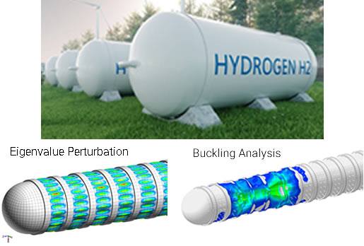
ASME “Design-By-Analysis” Buckling Classification of an In-Line Gas Pipeline Pig
Buckling of externally pressurized structures is a fascinating phenomenon and for those aficionados of classic old-time submarine movies, a bit of cold sweat. Predictive Engineering has significant experience in the buckling of structures using ASME’s PVHO and ABS’s Underwater Vehicles code for hyperbaric chambers, submarines, pressure vessels and now for an in-line gas pipeline pig. Our client manufactures sensor’s for pipeline inspection industry. A common method for delivery of the sensor is send a “pig” or a cylinder loaded with instruments through the gas pipeline driven by a differential pressure. Operating conditions within the pipeline can reach pressures up to 1,500 psi. To ensure that their instrument package could safely operate, they contracted us to perform an ASME Section VIII, Division 2 “design-by-analysis” study on the buckling resistance of their miniature in-line inspection tool or “pig”. Their material of choice was a simple carbon steel (L360MS). The ASME allowable stress was calculated using standard knock-down formulas where the material’s original yield strength of 66.7ksi was reduced to a membrane allowable of 16.2ksi. The buckling assessment was based on 2.08 safety factor. FEA simulation started with a linear elastic stress analysis followed by an eigenvalue buckling analysis. To verify the eigenvalue results, a geometric nonlinear buckling analysis was performed on the structure. As our client had suspected, the pig had significant safety margins and the project was sealed up and our project summary was one sentence “The ….. passes the ASME Section 8, Division 2 stress and buckling classification.”
Weld Fatigue Analysis of Overhead Condenser Tubesheet Intersection
Our client had a very specific challenge in dealing with a prior design that was failing after five to seven years in service. They wanted to extend the life of the vessel but given financial and design constraints had a very limited set of options. The tubesheet was explosively clad with titanium. The material selection was a combination of stainless steel and carbon steel. A combined thermal-stress (internal pressure + temperature differential) analysis showed high stresses at the weld intersection that was an obvious driving factor toward the shortened service life of the vessel. Further analysis pinpointed the problem to the use of stainless steel for the tubesheet given its high CTE would expand push against the shell. That is to say, the internal pressure load only created about 20% of the stress load while the thermal load was 80%. Various redesign attempts were explored to move the weld zone down and way from the tubesheet intersection via a “stub” approach but every attempt only slightly lowered the stresses. After numerous meetings, it was determined that the tubesheet could just as easily be made out of carbon steel and thus with its lower CTE solve the problem of high stresses at the weld zone. Although this was not a classic ASME Section VIII, Division 2 FEA stress analysis, the skill sets we have learned over the years through the FEA simulation of hundreds of pressure vessels allows us to offer unique solutions that our clients might not immediately think of. With the change of tubesheet materials, the client was able to more than achieve their goals by lowering the cost of fabrication and extending the service life of the vessel.
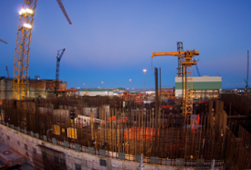
Nuclear Waste Processing Vessels
Seismic, thermal, dead weight, nozzle and pressure analyses were performed on a series of large-scale (e.g., 300” diameter) nuclear waste processing vessels for the DOE. Engineering work was approved under ASME Section VIII, Div. 2, ASCE 4-98 for Seismic Analysis of Nuclear-Related Equipment and associated NQA-1 requirements.
100 foot-long Tube and Shell Evaporator
A 100 foot-long tube and shell evaporator was analyzed for stress and deflection based under transportation loading. Stresses were classified according to ASME Section VIII, Div. 2. The evaporator was fabricated with several different material types, each with different ASME Division 1 material allowables. The vessel was constrained with a saddle support near the top tubesheet with a Schnabel connection at the base of the skirt.
Stress and Fatigue Analysis of a Powder Transfer Vessel
A standard thin-walled pressure vessel was analyzed to ASME Section VIII, Division 2 rules given an internal pressure and dead weight loading that consists of a granular powder. Besides the analysis of the pressure hull, the vessel’s supports were analysis for a combination of seismic and wind loading per ASCE 7 specification. After this classification, a fatigue analysis was done on the complete structure per ASME Section VIII, Div. 2, Part 5.
External Pressure Loading on Sensor Pig for Gas Pipelines: Stress and Buckling Analysis
Our client had a thick-walled vessel that would carry sensor equipment to monitor the structural health of gas pipelines. The external pressure on the vessel would be in excess of 1,000 psi. By careful use of the “design-by-analysis” rules within the ASME Section VIII, Division 2 code, we were able to take their original design and make it a bit lighter and substitute a much lower cost material. This flexibility allows one to leverage the full power of a finite element analysis to maximize the design of the pressure vessel structure.
Thermal-Fatigue Analysis of High-Temperature Flue Gas Steam Generator
An ASME thermal fatigue analysis was performed on a high-temperature flue gas steam generator (i.e., boiler). Given the large thermal gradients between the flue gas inlet and outlet, the thick tube sheet presented a particular thermal-stress challenge. The vessel passed based on peak alternating stress (Sa) per Figure 5.110.2.1 of the ASME Section VIII, Division 2 code. This particular PV FEA consulting project was reviewed at several levels from the manufacture to their end-client. We sat in during the review defending our work and were able to successful get the vessel to pass muster without last minute design changes.
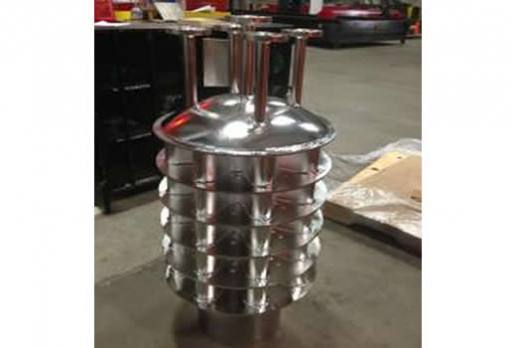
Thermal-Stress and Fatigue Analysis of Thick-Walled, High-Pressure Liquid Oxygen (LOX) Tank
Thick-wall, high-pressure liquid oxygen (LOX) tanks experience thermal fatigue conditions not rarely seen in normal pressure vessels. Stress classification required our complete ASME software arsenal. Membrane stresses were calculated using standard ASME stress linearization. These tanks were used in test firing of rocket nozzles where one set of tanks stored LOX and the other set RP1 (rocket fuel). All vessels were classed under ASME Section VIII, Division 2 rules.
ASME Section VIII, Div. 2 Pressure Vessel Transportation Analysis
The PV in this FEA consulting analysis was a large shell-and-tube heat exchanger analyzed under transportation conditions. The project required the design of the shipping support structures: a schnabel at the skirt and a saddle at the upper tubesheet. Once the static stress analysis was performed, the results were interrogated to ensure that the stresses within the PV did not exceed the ASME allowables (PL, PM for membrane stress and PL+PB+Q for surface stress) and the stresses within the support structures did not exceed AISC N690 stress allowables.
ASME Section VIII, Div. 2 Pressure Vessel Lifting Analysis
In this analysis the PV was analyzed for lifting loads at various angles as the vessel is installed. The main concern was the skirt, tailing lug and trunnions. The mass of the vessel was a critical parameter. To ensure proper mass was include the finite element model used beam elements to approximate the tube sheet; this greatly improved the efficiency of the model. Initially, the tailing lug was not adequate but after a couple design suggestions a final design was found.
ASME Section VIII, Div. 2 Pressure Vessel Reorientation Analysis
A large (100’”) ASME Section VIII PV needed to be reoriented within the fabrication shop to provide access to allow test fitting of external structures. This analysis helped determine the most effective combination of rollers and belly-bands that will allow the C210 Evaporator Vessel to be rotated to provide access for test fitting ladders and platforms while not exceeding ASME Section VIII Div 1 stress allowables.
Stress Analysis of Shell and Tube Heat Exchanger
The pressure vessel system consisted of an evaporative chamber connected to a tube-sheet heat exchanger via piping. The system is mounted on a structure steel frame. Thermal and stress analysis calculations were performed per ASME VIII, Div. 2 to determine thermal and stress margins. Some optimization work was done on the lower piping system due to wind loading effects per ASCE 7-02.
Thermal-Stress Analysis of Dual-Chamber Titanium Shell and Tube Heat Exchanger
Shell and tube heat exchanger for a boiling tube, dual-vessel evaporative system classed under ASME Section VIII, Division 2 rules. The main shell was titanium with the tubing of SA-240. The vessel analysis included a check on the tube sheet design and optimization work to reduce the wall and tube sheet thicknesses due to high material costs. Design and analysis work was performed for the Dedert Corporation.
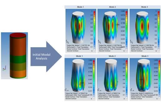
Stress, Buckling and Seismic Analysis of T-Design Shell and Tube Heat Exchanger
Shell and tube heat exchanger per ASME Section VIII, Div. 2 analyzed for design, operating, buckling and seismic loading. The final design of the vessel required 14 design iterations due to internal baffle constraints to prevent buckling. The final buckling analysis was done by geometric, nonlinear analysis to confirm safety margins.
Stress, Thermal-Stress and Buckling Analysis of Dual-Wall 5.8m Diameter Valveless Regenerative Thermal Oxidizer (VRTO) Vessel
The VRTO was analyzed for stress, thermal-stress and buckling per ASME Section VIII, Division guidelines and with all results classed per Division 1 stress allowables. This large diameter vessel is used to efficiently burn-off process gases using a unique regenerative ceramic bed. Process gas is introduced through the bottom of the vessel into the ceramic bed which allow selective heat transfer from the ceramic to the gas stream. Without going into a lot of detail, the analysis work considered thermal expansion effects within the vessel due to the hot gas at temperatures above 500C and load combination effects due to internal pressure and external wind loading. The vessel was classed to include super-structure loading (roof mounted blowers and a walkway), dead weight loads (ceramic and steel) and then normal design loads.
The VRTO vessel passes the ASME Section VIII, Division 2 requirements for mechanical and thermally-induced stresses. It should be noted that the VRTO vessel is not an ASME stamped vessel and there is no requirement for it to be classed under the ASME code, saying that, the code provides sound guidance for verification of its “fit-for-service” design. The vessel was classed using the ASME stress allowables for 316L. An optimization study was also done to investigate the roof-to-shell weldments for possible improvements in the manufacturing process and to investigate a material switch from AL6NX to standard SS304 or at least the ability to thin the shell material from 0.125 to 0.1875”.
At the end of this project, optimization results more than paid for the cost of this FEA investigation.
Large Diameter Spray-Drying Chamber
A large diameter spray-drying chamber was analyzed for seismic, wind and lifting. Applicable codes were ASCE 7-02 with reference to the UBC and ANSI A58.1. The lifting stress requirements were borrowed from ASME, Section VIII, Division 2. The model was highly idealized and allowed sections to be optimized for seismic and lifting. The exterior of the vessel was a space frame structure idealized using beam elements. Appurtances hanging on the outside of the vessel (e.g., fans, heaters and ladders) were simulated using mass elements.
ASCE 4-98 Pressure Vessel Sloshing
For this project, the sloshing loads needed to be determined within an ASME Section VIII, Div.2 Pressure Vessel (PV) upon a large marine vessel. The fluid sloshing pressure loads were calculated with ASCE 4-98. The 3D spatially varying loads were applied to a Finite Element (FEA) model. The FEA model provided reaction loads and stress results used to design anchors and determine potential problem areas in the skirt.
Thermal-Stress Analysis of a 500 kW Generator Housing
This project involved FEA modeling, meshing and analysis of integrated power module generator housing. Model loading included thermal loads, pressure loads, static forces and interference fits. The housing was evaluated against ASME Section VIII, Div. 2 allowables.
ASME Section VIII Pressure Vessel - Iterative Vessel Design and Analysis
It is common for a PV to have non-standard geometry that requires ASME Section VIII, Division 2 analysis. If the majority of the components of the vessel are radically different from the standard components of an ASME Section VIII vessel, initial section sizing must be determined with an FEA model.
This project started with initial design proposed by the manufacturer. An efficient FEA model was constructed and multiple iterations were performed, updating the section thicknesses until a workable design was achieved. Once a workable design had been achieved, there was freedom to explore different shell shapes, stiffener geometries and flange thicknesses. The vessel evolved from something that was simply “workable” to something with optimal wall thicknesses and surface area that met the thermal requirements of the project.
Thermal-Stress and Fatigue Analysis of Dual-Material Tube Sheet Bundle
Very large ASME vessel analyzed for tube-sheet stresses arising from dual-material tube-bundle with likewise dual material shell. Thermal-stress analysis was performed to classify system under ASME stress and fatigue requirements.
Lifting Analysis of As-Built Pressure Vessel
A complex lifting analysis was performed to verify that an already built vessel system would not exceed ASME Section VIII, Div. 1 allowables. The slings and spreader bar were idealized with beam elements and pinned connections.
Stress and Buckling Analysis of Deep-Diving Submarine
Finite element analysis of an eight passenger, deep-diving (depth 1,200’) luxury submarine under ASME Section VIII, Division 2 rules. Stress results were verified by strain gauging of the submarine during its submersible proof-test. Given the close correlation of the stress results to the dive test, it become the first human occupancy submersible certified by the American Bureau of Shipping (ABS) via the finite element method. Two other submarines were likewise analyzed.
Stress Analysis of Formaldehyde Reactor
Formaldehyde reactor analyzed for thermal and mechanical performance. ASME Section VIII, Div. 2 code requirements on internal shell and tube heat exchanger.
Threaded Plastic Regulator with Pressure Load
A static stress analysis was performed on a threaded plastic regulator. This analysis required that the FE model was built with fine detail in key locations but reasonably low overall model size for quick and efficient solve times. These key locations include area of high stress (as determined by pilot models), threaded regions and areas in contact. Although not classed as an ASME pressure vessel, this small pressure vessel required the same type of analysis procedures to numerical proof the design.
ASME Section VIII Pressure Vessel - Fluid Mass Adjustment with Software Automation
Since thin walled PV FE models are most commonly built with plate and beam elements, the mass of non-structural three dimensional entities (i.e. fluid, concrete, insulation) must be distributed over the surface area or length of corresponding mesh. Fluid mass must be changed to adjust the FEA model for horizontal or vertical seismic analyses.
Using a Microsoft Excel spreadsheet and Femap's Application Programming Interface (API), a “Non-Structural Mass (NSM) Adjuster” was created to rapidly add, remove or change the FE PV. The Excel-based API uses the volumes of the components, material densities and plate mesh surface areas to calculate NSM values for the model. The program allows the user to change the NSM of the FEA model with a single button-click. When the user selects horizontal or vertical seismic conditions, the API distributes the NSM while maintaining an accurate center of gravity.
ASME Tube and Shell Heat Exchanger Vessel
Based on an initial design as developed by TEMA and ASME codes, a large pressure vessel was analyzed under ASME Sec 8, Division 2 specifications with a complete seismic and buckling analysis. An interesting twist to this vessel analysis was that it was based on the client’s existing vessel and was woefully under-designed for its intended application. Although one may take analysis work for granted, it is very easy to produce wrong numbers. Predictive Engineering takes great pride that it has never delivered bad results to a client and that in over 17+ years of service, not one component analyzed by Predictive has failed due an analysis error.
Submarine Analysis Work via ABS and ASME Codes
Predictive engineering has certified two large, manned commercial submarines and a third experimental submarine destined for the Mariana Trench. We have extensive experience in ABS and ASME PVHO codes that allows us to guide the client toward the most optimized design for a manned submersible. Complete FE analysis can be done with a nonlinear buckling calculation to validate the submarine design. Our work has been strain gauged and validated under ABS surveyor requirements.
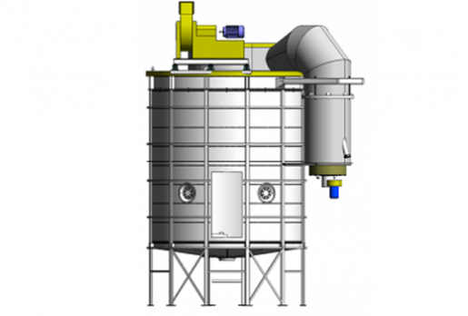
Regenerative Thermal Oxidizer (RTO)
The RTO contains a heat exchanger mass divided into sections – each part alternately serves the cooling phase, while the other serves the heating phase. The exhaust air flows through the RTO’s heat exchanger mass from bottom to top, which heats it up to oxidation temperature – approximately 800 °C. The hot purified gases then flow downwards through the other part of the heat exchanger mass, giving it their heat.
A finite element analysis (FEA) model of the RTO was built and subjected to pressure, dead weight and thermal loads. The first objective of this analysis was to ensure that the pressure boundary met ASME allowables under pressure, dead weight and platform loading. Because the vessel is designed to be subjected to a negative pressure load and a compressive load exists on its roof, a buckling analysis was performed per the ASME code. The second objective of this analysis work is to investigate the penetrations (nozzles and platform standoffs) connecting the inner and outer wall on the roof. With the inner wall at a higher temperature than the outer wall, differential expansion has the potential to create high stresses at these connections.
Horizontal Pressure Vessel Mounted on Sliding Frame
When a fabricator was hired to build pressure vessels from an existing design, a bit of reverse engineering was necessary. While the code calculations for the pressure boundary and nozzles were straightforward, the support system was a bit more complicated. The vessel is oriented horizontally and mounted to a support frame at the top head and along the shell. The vessel able to open at a set of retaining rings between the shell and top head. Once the swing bolts are removed, the vessel shell and bottom head slide away from the top head using a gantry system.
The analysis of this system required two loading conditions. First the vessel was analyzed in the “closed” position. That is, the vessel shell was attached to the top head at the retaining rings. In the closed position, the vessel is at maximum fluid level with maximum design pressure. The second load combination had the vessel in the “open” position. In the open position, the vessel is not pressurized and does not have fluid contents. This load combination needed to be considered because with the vessel shell detached, the cantilevered loads at the top head supports are increased.
ASME Pressure Vessel Analysis
Extensive experience has been earned in the analysis of dozens of simple to complex pressure vessels. Vessels have been certified under ASME Section VIII, Division 1 and 2 with every possible configuration of tube sheets, nozzle connections, partitions and operations. Work has also been executed under NQA-1 for extremely complex nuclear waste recycling vessels in seismic environments. Buckling analysis was done via ASCE and ASME requirements. In some cases, the buckling resistance of the vessel was certified by UG-2 exception using a non-linear approach to the structure. A complete rainflow counting fatigue analysis was also performed on all structural components, weld joints and piping structures.
The Hydrogen Economy – Go Green or Go Home
Why Simulation? Get It Right, Know Your Margins, In Service Confidence (Fracture and Fatigue)
The hydrogen economy is coming—not because of social interest or politics, but because of capitalism.
FEA Application for Industrial Equipment
Finite element analysis, or FEA, is a powerful tool for evaluating structural performance under realistic operating conditions.
ASME BPVC Fatigue Analysis – Part 5.5: Protection Against Failure from Cyclic Loading
Besides providing robust fatigue curves, the Code provides explicit guidance on how to treat welds based on type, inspection and surface quality. For example, if the weld is completely un-inspected and un-finished, then it earns a fatigue-strength-red
ASME Section VIII Pressure Vessel - Nozzle Load Application with Software Automation
Finite element analysis can quickly provide accurate stress numbers for a complete range of nozzle and shell configurations. What is not well-known is that this process can be automated.
Large Pressure Vessel Lifting Analysis
When dealing with large pressure vessels lifting and transportation can be challenging. ASME Section VIII code drives the design of the vessel but only includes details on operational loads. Lifting and transportation is a critical aspect with s
Design-by-Analysis - Nonlinear FEA Elastic-Plastic Stress Classification
Upon closer inspection of the stress results, it was noted that the non-complying high stress regions were localized and that the surrounding steel had stresses mostly below the yield stress of the material.
Optimization of Cryogenic Pressure Vessel for Rapid Heat Transfer Analysis
What if the majority of the components of the vessel are radically different from the standard components of and ASME Section VIII vessel? How is initial section sizing determined?
ASME Section VIII, Div 2 High-Pressure LOX Tank Analysis
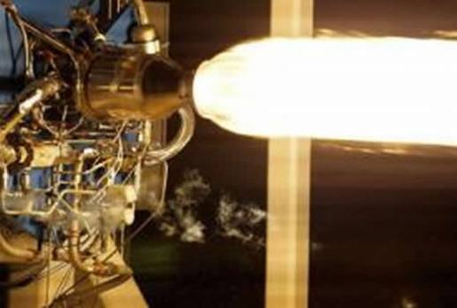
The development of the next generation of rocket motors requires extensive testing and that means lots of repetitive live firing. These motors are feed with a standard mixture of high-grade kerosene or RP-1 and liquid oxygen (LOX). The fuel supp
ASME Section VIII, Division 2 Fatigue Analysis of Pressure Vessels and Heat Exchangers
Within the ASME Section VIII, Division 2 code, the design-by-analysis requirement provides significant flexibility to ensure that non-standard designs will be safe for service.
Seismic, Stress, Thermal, Fatigue and Sloshing Analysis of Nuclear Waste ASME Pressure Vessels
The design and manufacture of pressure vessels might be considered a bit staid and old-fashioned by many engineers where one simply cranks through pages of arcane Code to create the proverbial bomb-proof design. For our client this might have been the
Over the last 20+ years, Predictive Engineering has tackled some of the most complex applications of the ASME BPVC Section VIII, Division 2 specifications.
- Stress and fatigue analysis of large-diameter nuclear waste recycling vessels under NQA-1 requirements
- Vessels with internal piping and structures subjected to sloshing, seismic and added-mass effects
- Transient thermal-fatigue of
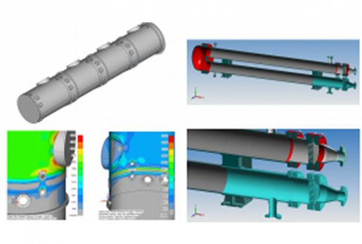
ASME Section VIII, Division 2 Pressure Vessel - Transportation Analysis
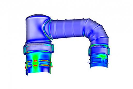
The pressure vessel in this analysis was a large shell-and-tube heat exchanger analyzed under transportation conditions. The heat exchanger was idealized with a combination of plate and beam elements as shown in Figure 1. One end of the vessel w
Thermal Stress Analysis of Large-Scale Evaporator-Condenser Set
ASME Section VIII, Division 1 rules can be overly conservative or may not be directly applicable to unique combinations of thermal, pressure, and possibly external primary or secondary loadings.