CFD Simulation of Recovery Boiler Combustion
Analysis
Objective
A CFD analysis was performed on a newly built recovery boiler to estimate operational temperatures, CO emissions, and NOx emissions.
Predictive Engineering has been working closely with SHB Power Plant Engineering on the modeling of bio-fuel power generation in STAR-CCM+.SHB is a local company in Portland, Oregon that specializes in upgrading boilers to increase efficiency and reduce emissions. This has been a unique project that has involved software support for Simcenter STAR-CCM+, engineering consulting services, and technology transfer so that SHB can run the models in-house for further design exploration.
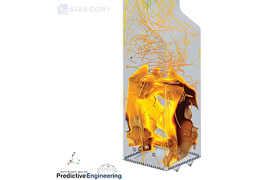
Combustion is one of the most challenging types of analysis to solve through CFD and the analysis requires a highly capable code with strong multiphysics capabilities. Predictive Engineering developed a model of a recovery boiler for SHB in support of on-going efforts to evaluate performance and identify areas of improvement. Recovery boilers are used in the paper-mill industry and are fueled by black liquor, which contains wood lignin from the pulping process. Although the black liquor is a highly viscous liquid, we utilized the coal combustion model in STAR-CCM+ to simulate the multistage combustion process of solid biomass fuel from drying, devolatilization, char burning, and reduction to ash/inert components. Combustion of the devolatilized gases within the lower furnace is handled by an eddy-break up model utilizing reversible reactions to provide a quick estimate of flame locations, energy release, and CO production. The model utilizes a built-in thermal NOx model utilizing the Zeldovich mechanisms to predict NOx formation from the combustion process. Radiation and conjugate heat transfer to the surrounding tube walls was modeled utilizing gray gas, participating media models.
One of the most challenging aspects to modeling black liquor combustion is to capture the unique swelling that occurs during combustion. As the injected black liquor droplets dry and devolatilize, the particles can swell 4 to 5 times the original size. This size expansion causes the lighter particles to lift up within the lower furnace. Once char burning commences, the particles shrink back in size and fall to the char bed below. To capture this effect, standard drag models were customized and tuned to meet the desired behavior.
PDF Download


