Extreme Implicit Nonlinear Analysis of Plastic Thread Design
Analysis
Objective
The genesis of this project came about to validate a prior consultants work indicating that the thread design of a new device would fail right at the design load of the instrument.
Since the company had experimental data which strongly indicated a failure load of 2x the design load, there was a whirlwind of debate as to whether to proceed to mass production or conduct an extensive redesign campaign. Although I entered this project with high confidence I soon realized what a quagmire I had entered. Initially I thought the analysis work could be accomplished using a standard implicit nonlinear code and after a few days of frustrating keyboard pounding I soon realized that I needed more horsepower. I was against the wall and it was time to pull out the big guns: LS-DYNA. Initially I was a bit hesitant to use LS-DYNA since I wanted to maintain the analysis procedure within the implicit world and historically LS-DYNA was a bit weak on the implicit side. Well, welcome to 2005 and V971 of LS-DYNA. Based on my experience with this project and prior experiences, I can clearly state that LS-DYNA has made great strides in the implicit realm. That is to say, LS-DYNA has always been dominant on the explicit side while its implicit capabilities were considered more of a sub-set. With the release of V971, the implicit capabilities within LS-DYNA are now a threat to the more established implicit nonlinear codes.
Initially, the LS-DYNA results for the thread design matched up with the original consultants work. This was depressing since the experimental work indicated a 2x load factor and I knew that LS-DYNA could do better. Digging in and making several calls to the technical support staff at LSTC, a recommendation was made to use *MAT PLASTICITY COMPRESSION TENSION (*MAT 124) along with several other tweaks to the implicit solver routine. The utility of this material model is that one can use different stress/strain curves and failure limits for compression and tension. This was absolutely fantastic for the plastic material used for the thread design since the failure stress for the plastic under compression is about 3x higher than that for tension. With these changes in place, the LS-DYNA model predicted a failure load of 2x the design load. This was very gratifying since the material stress/strain curves were not "adjusted" and used straight out of the gate.
At the end of this project, the client was able to rest assured that the design was robust and we also learned many other cool things about plastic thread design, but they are of course, proprietary.
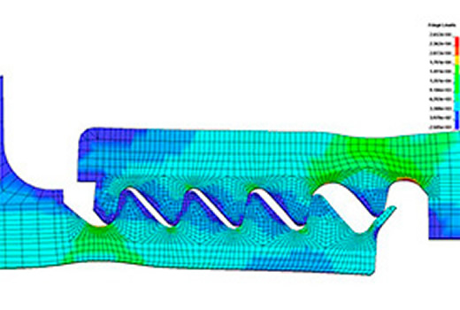
Modeling Notes: The 3-D geometry was provided in the form of a Pro/E STEP file and imported directly into Femap V9.0.1. The model exploited the geometric and loading symmetry of the structure and only a 5 degree segment was required to capture the mechanical response of the device. The model was carefully meshed to obtain a fine grid of 8-node brick elements. Contact elements and other analysis specific tweaks were done within LSTC’s LSPOST (a pre- and post-processor for LS-DYNA). A complete implicit analysis run would take about 5 minutes on a standard single-processor Intel PC.
The material model was *MAT 124 and data was derived from tensile test data provided by the client. Compression test data was inferred from theory and general data trends for this material. The model was run to the failure point of the plastic.
All analysis work was done with LS-DYNA V971.
PDF Download


