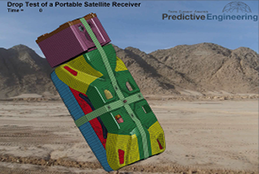
LS-DYNA FEA Simulation of Drop Test per MIL-STD 810e of Carbon and Kevlar Composite Electronic Device
Analysis
Objective
An ultra light-weight carbon and Kevlar fiber composite electronic device was drop tested through a range of 26 positions (MIL-STD 810e). The shell of the unit was a blend of carbon and Kevlar layers for increased impact resistance. The finite element model was used to document experimental drop test failures and then to implement solutions. The modeling results were reviewed by a team of external experts and accepted for production.
.Introduction: An advanced electronic device with a composite protective shell of carbon fiber, kevlar and standard fiberglass was drop tested using LS-DYNA. The drop test procedure followed that as given by a MIL-SPEC 810e sequence of 26 drop positions that theoretically envelopes all possible drop scenarios.
The LS-DYNA model was constructed using plate and hex elements for all major structural components. The carbon fiber and glass fiber (FRP) composite structures were modeled using LS-DYNA’s composite elements via *PART_COMPOSITE. Failure predictions were made within major structural sections by an assessment of plastic damage. The construction of the FE model was based on numerous simplifications that are not always the easiest to justify in strict analytical terms but are based on proven past techniques that have been shown to generate acceptable results.
The major structural components of the system were its carbon/Kevlar shell components along with the glass-fiber (FRP) antenna base. The antenna was connected to its azimuth drive via a carbon fiber tube. The azimuth drive motor housing was made of die-cast magnesium and was idealized using a combination of brick and plate elements to capture its variable thickness geometry. The drive motor and other significant weight components were model using mass elements.
Drop-test results from the model were shown to accurately predict two of the three noted failures in the device. The third failure not noted in the FEA model was vigorously debated in several meetings with the client (the manufacturer) and their end client (government). Predictive suggested that a metallurgical analysis be performed on the die-cast magnesium azimuth drive housing at the base of the antenna. Results from this analysis showed massive porosity that aligned perfectly with the cracks observed from the drop-test. Given this observation, the client concluded that the FEA model had accurately predicted all failures and lend to an improved process specification by its null result finding.
The finite element model was constructed using Femap and analyzed using LS-DYNA.
PDF Download
LS-DYNA FEA Simulation of Drop Test per MIL-STD 810e of Lightweight Carbon and Kevlar Composite Shelled Electronic Device


